Beta Draft Confidential
Installing and Removing Modules
Installing or Replacing Power Supplies
CBX 500 Multiservice WAN Switch Hardware Installation Guide 4/5/036-27
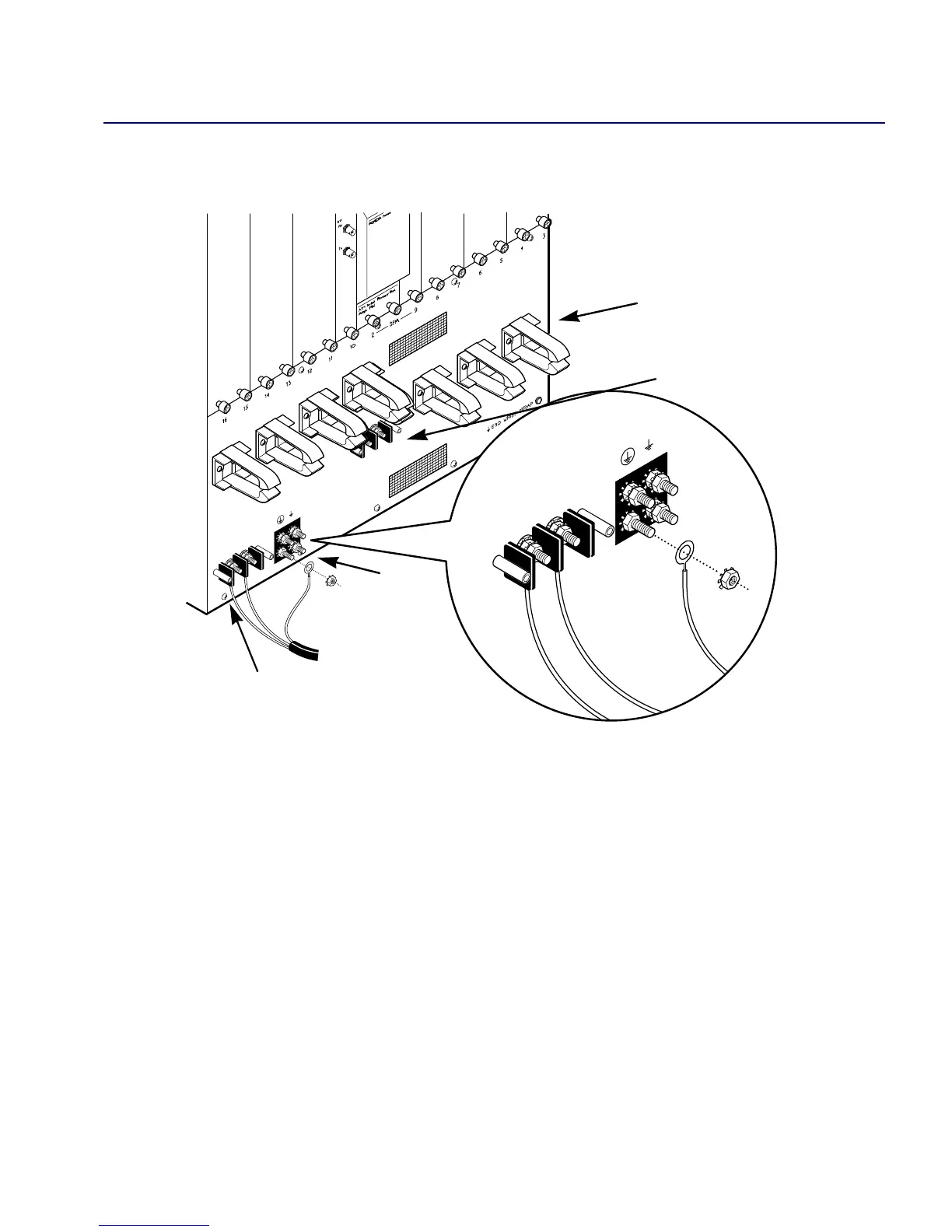
Figure 6-12 shows the Power Distribution Unit for a -48 VDC power supply module.
Figure 6-12. Power Distribution Unit for a -48 VDC Power Supply
Although the AC and DC power supply modules look different, the removal and
replacement procedures are identical except for the power cord connection. Both AC
and DC power supplies are removed from the front of the switch.
POWER FEED B
–48VDC
RTN
POWER FEED B
–48VDC
RTN
POWER FEED A
–48VDC
RTN
Secondary Power Supply
Connectors
Ground
CableStrainReliefClamps
Primary Power Supply
Connectors