INSTALLATION INSTRUCTIONS
7. Using an M 16 socket, remove the two bolts (A) holding
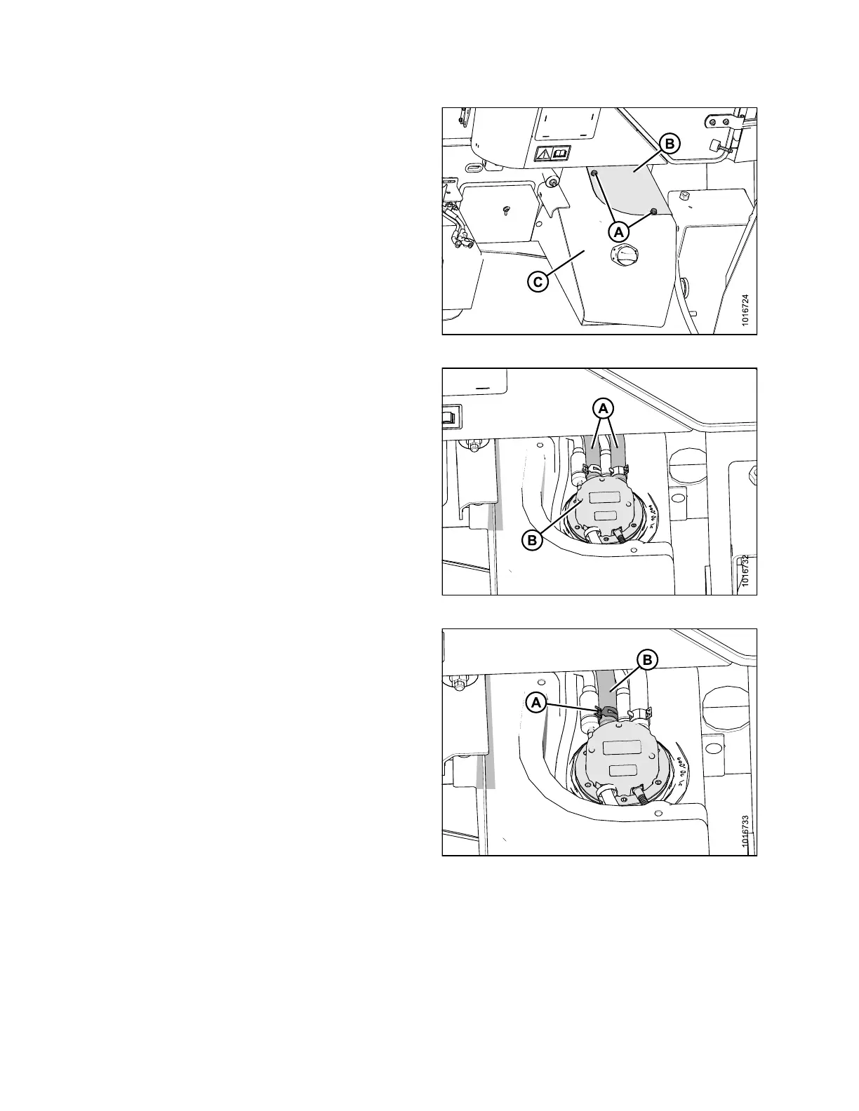
the DEF tank cover (B) to the DEF tank as sembly (C).
Retain bolts for use later.
8. Remove the DEF tank cover (B) and set aside.
Figure 3.25: DEF Tank Assembly
9. Pinch shut with clamp or similar means, the black
and red coolant lines (A) coming to the DEF head (B)
approximately 6 in. (152 mm) from head, in order to
keep engine coolant from draining when hoses are
removed in the next step.
Figure 3.26: DEF Head
10. Usin g a
pair of constant tension clamp pliers, loosen
the co
nstant tension clamp (A) on the black (return)
coola
nt line (B).
Figure 3.27: DEF Head
167730 20 Revision B