ASSEMBLING THE W INDROWER
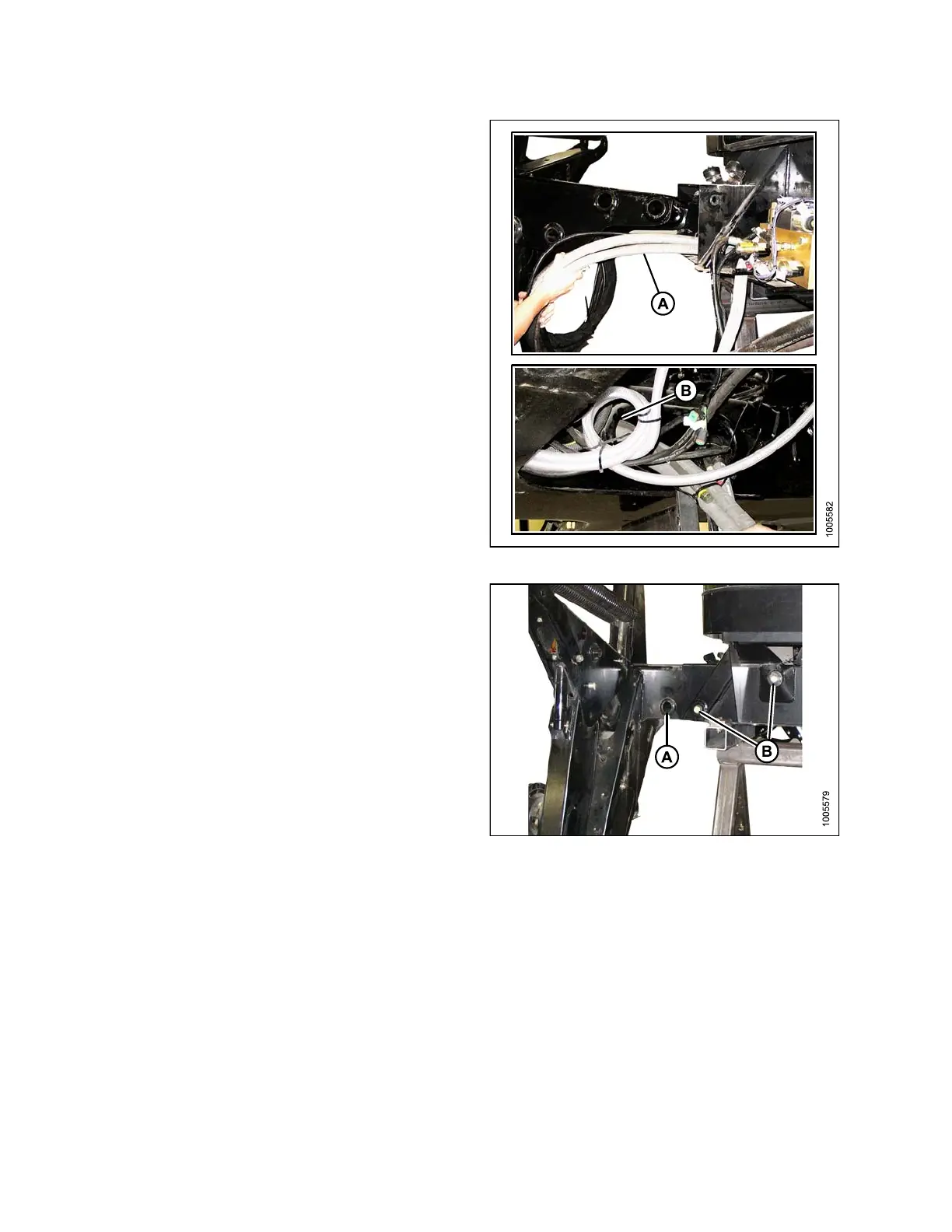
4. Feed the hydraulic hose bundle (A) into the frame and
through the hole (B) at the center of the frame.
Figure 3.
10: Hydraulic Hoses
5. Inse rt the leg into the frame and line up the holes in the
frame and the leg at the first position (widest tread with
one exposed hole [A]).
6. Insert pins and secure with 3/4 x 16-1/2 in. long
bolts (B), washers, and nuts. Torque t o 136 N·m
(100 ft·lbf).
7. Repeat for opposite leg.
Figur
e3.11:LegPositiononFrame
147962 32 Revision A