UNLOADING AND ASSEMBLY
169561 22 Revision C
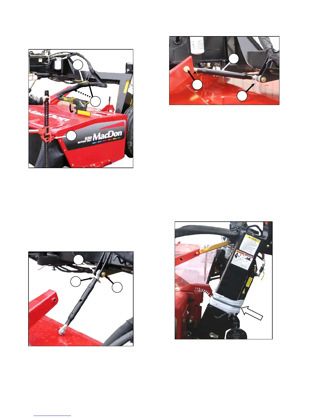
STEP 12. INSTALL CENTER-LINK
a. Lift front corner of header using a lift jack (A)
until the shipping brace (B) is loose.
b. Remove clevis pins (C) securing brace to
header and carrier frame, and remove brace
(B). Retain pins for re-installation.
c. Lower header to ground.
d. Raise front of APT hitch with the jack to allow
installation of the adjustable mechanical
center-link or optional hydraulic link.
A. MECHANICAL LINK
a. Attach mechanical link (D) to carrier frame with
clevis pin (C). Secure with cotter pin.
b. Loosen nut (E).
c. Rotate the turnbuckle sleeve (F) so that link can
be connected to header. Insert clevis pin (C)
when holes are aligned, and secure with cotter
pin.
d. Rotate sleeve (F) to approximately mid-position.
e. Snug up nut (E), but do NOT over-tighten.
A slight tap with a small hammer is sufficient.
B. HYDRAULIC LINK
a. Refer to instructions provided with hydraulic
center-link kit for installation procedures.
STEP 13. REMOVE BANDING AT
LIFT CYLINDERS
a. Cut the banding that secures the LH and RH lift
cylinders to the carrier frame.
C
F
E
B
C
A
E
C
D