41
MagCore® Plus II
Signal pathway:
Sensor → Sensor Cable → PCB → PLC → PCB → HMI
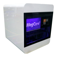
1. Check if the SENSOR working properly:
Check PLC – X12 should light up when the sensor is ON and turn off when the
sensor is OFF:
Machine is turned on.
Sensor is working properly,
LED is on.
Place an object next to the
sensor → LED will turn off.
Remove an object → LED
will turn back on.
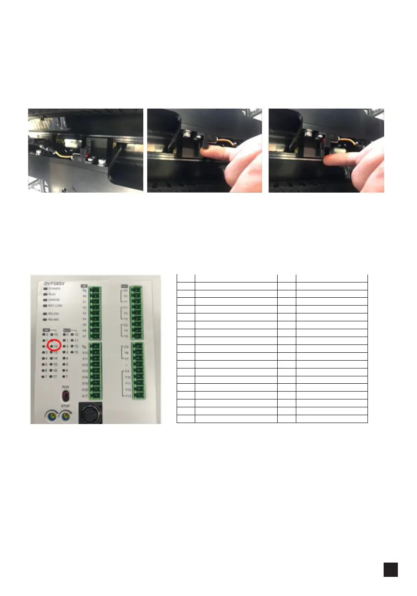
Checking Signal Propagation
I/O IN I/O OUT
X0 Y Motor Encoder Signal(A) Y0 Y Motor Drive(A)
X1 Y Motor Encoder Signal(B) Yl Y Motor Drive(B)
X2 Y Home Sensor Signal Y2 V Motor Drive(A)
X3 Y3 V Motor Drive(B)
X4 V Motor Encoder Signal A Y4 X Motor Drive(A)
X5 V Motor Encoder Signal B Y5 X Motor Drive(B)
X6 V Home Sensor Signal Y6
X7 UP Sensor Signal Y7
X8 Y8
X9 Y9
X10 X Motor Encoder Signal(A) Y10 M DC Motor JOG
X11 X Motor Encoder Signal(B) Y11 UV Lamp Switch-Relay
X12 X Home Sensor Signal Y12 RS232 Switch
X13 Down Sensor Signal
X14
X15
X16
X17 Door Sensor
 Loading...