A general purpose installation does not have flammable
media present. Areas rated non-incendive (Cl I, Div. 2) have
flammable media present only under abnormal conditions.
No special electrical connections are required so standard
installation methods may be followed.
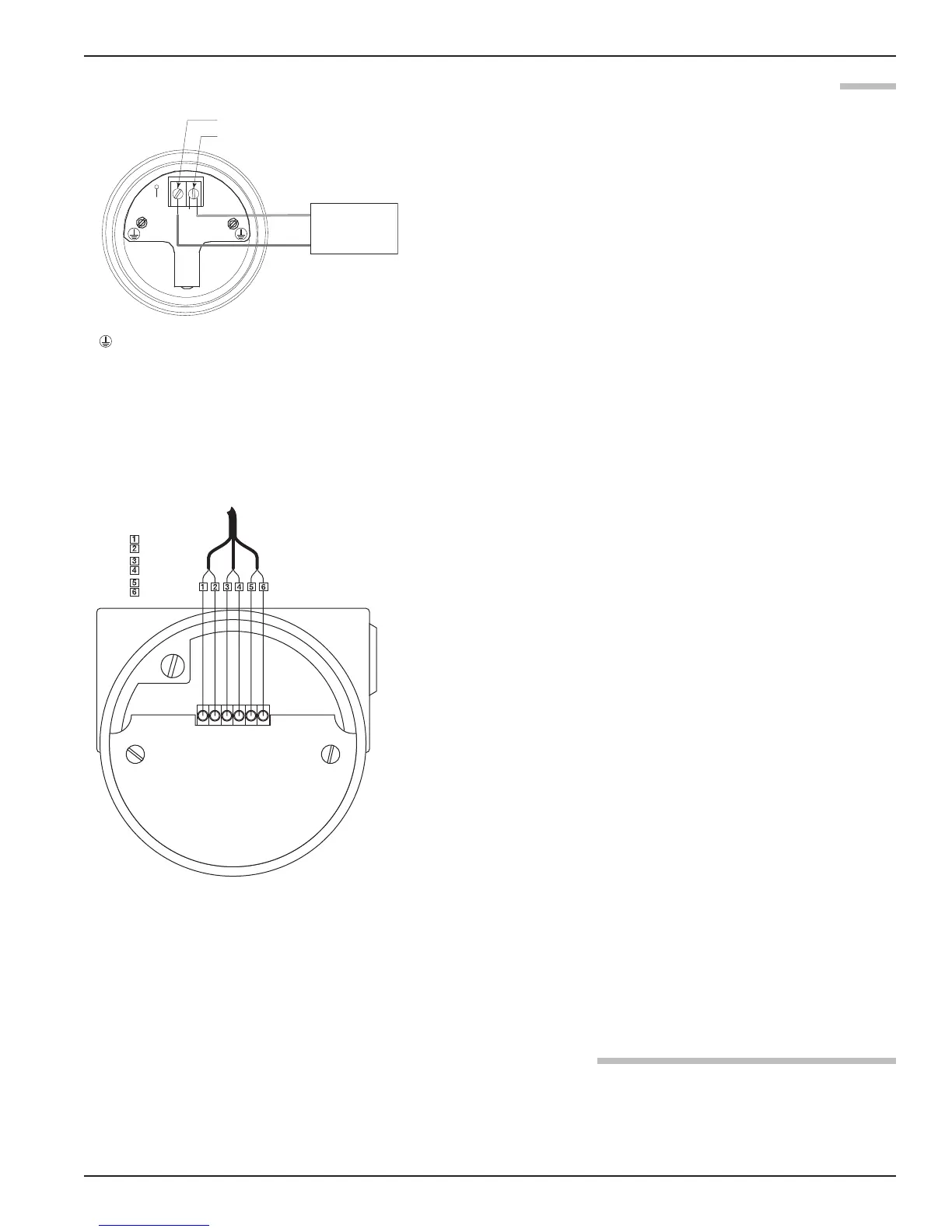
To install General Purpose or Non-Incendive wiring:
1. Remove the cover to the wiring compartment of the trans-
mitter. Install the conduit plug in the unused opening. Use
PTFE tape/sealant to ensure a liquid-tight connection.
2. Install a conduit fitting and pull the supply wires.
3. Connect shield to an earth ground at power supply.
4. Connect an earth ground wire to the nearest green ground
screw. Use a minimum 18 AWG rated up to 85 °C.
5. Connect the positive supply wire to the (+) terminal and the
negative supply wire to the (-) terminal.
6. Replace the cover to the wiring compartment of the
transmitter.
To install Remote Mount wiring:
1. Install conduit from the remote mounted head to the
integral conduit connection of the E3 transmitter (refer to
local plant or facility procedures).
2. Remove the cover of the remote transmitter, terminal board
housing and of the integral terminal board housing.
3. Connect one end of the six conductor cable (P/N
037-3226-xxx or 037-3227-xxx) to the integral terminal
block and the other end to the terminal block within the
remote terminal board housing. Be sure to match the six
discrete numbered wires with the numbers on each terminal
block. See Figures 12 & 13.
4. Connect shield to an earth ground at the power supply.
5. Connect an earth ground wire to the nearest green ground
screw per local electrical code (not shown in illustration).
6. Connect the positive supply wire to the (+) terminal and the
negative supply wire to the (-) terminal.
7. Replace the covers to the wiring compartment of the
transmitter and to both terminal board housings. Ensure
that all covers are completely tightened down before apply-
ing power.
An intrinsically safe (IS) installation potentially has flamma-
ble media present. An approved IS barrier must be installed
in the non-hazardous (safe) area. Consult factory for agency
drawing.
15
48-640 E3 Modulevel
®
Displacer Level Transmitter - FOUNDATION fieldbus
™
+
–
Power Supply
2
4 VDC
(-) negative
(+) positive
Protective Conductor Terminal
123456
W
hite
Black
G
reen
B
lack
R
ed
B
lack