23
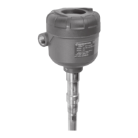
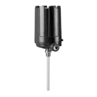
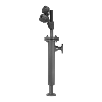
48-640 E3 Modulevel
®
Displacer Level Transmitter - FOUNDATION fieldbus
™
Should the E3 require replacement of any parts in the field,
a user calibration must be performed after changing out any
of the following original parts: Bezel assembly, LVDT
assembly, range spring, stem assembly, or displacer. The fol-
lowing procedure should be followed when performing a
user calibration in the field.
NOTE: For user calibrations, the factory calibration parameters will not
be incorporated into the level measurement.
1. Move liquid level on displacer to desired low level point.
2. Using the keypad and LCD display, scroll down to DispFact
3. Press
,
to access data entry mode, then until “Yes” is
displayed and again. The factory menu is now accessi-
ble.
4. Scroll down to CalSelct.
5. Press , then until “User” is displayed and again.
6. Scroll to “User Cal Menu” and press .
7. Scroll down to SnrCalLo.
8. Press , then and simultaneously and again.
The current sensor output has been captured for the low
level point.
9. Scroll down to LvlCalLo. The default value is 0.00. If a dif-
ferent level value is desired at this point, press , use the
and arrows to choose the desired value and press
again.
10. Move the liquid level on displacer to the desired high level
point.
11. Scroll to SnrCalHi.
12. Press , then and simultaneously and again.
The current sensor output has been captured for the high
level point.
13. Scroll down to LvlCalHi. The default value is an arbitrary
length. Press , use the and keys to choose the
desired value and press again.
14. The user calibration is complete.
NOTE: The original factory calibration settings are restored when
“FACTORY” is selected for “Calibration_Select” parameter.
It is highly recommended that factory calibration be used
for optimum performance.