41
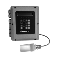
57-645 Eclipse Guided Wave Radar Transmitter - PROFIBUS PA
™
7.3 Specifications
Measurement Principle Guided time-of-flight via time domain reflectometry
M
easured Variable Level, determined by the time-of-flight of a guided radar pulse from
transmitter to product surface and back
Zero and Span 6 inches to 75 feet (15 to 2286 cm)
Keypad 3-button menu-driven data entry and system security
Indication 2-line × 8-character display
Digital Communication PROFIBUS PA
™
Profile Version 3.0, MBP (31.25 kbits/sec)
Minimum Operating Voltage 9 VDC
Quiescent Current Draw 15 mA
DEV Revision 0X01
Function Blocks AI_1, AI_2, AI_3, AI_4
Damping Adjustable 0-10 seconds
(Measured at instrument terminals)
General Purpose/Explosion Proof 9 to 32 VDC (15 mA maximum current draw)
IS/FISCO/FNICO 9–32 VDC (15 mA maximum current draw)
Material Aluminum A356T6 (<0.20% copper), optional 316 stainless steel
Cable Entry
3
⁄4" NPT and M20
Operating Temperature -40 to +175° F (-40 to +80° C)
Display Function Operating Temperature -5 to +160° F (-20 to +70° C)
Storage Temperature -50 to +175° F (-40 to +80° C)
Humidity 0-99%, non-condensing
Electromagnetic Compatibility Meets CE Requirements: EN 50081-2, EN 50082-2
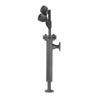
Note: Twin Rod and Single Rod probes must be used in metallic vessel or
stillwell to maintain CE requirement.
Mounting Affects: Twin Rod: Active rod must be mounted at least 1" (25 mm) from any surface or
obstruction. Minimum stillwell diameter for Twin Rod probe is 3".
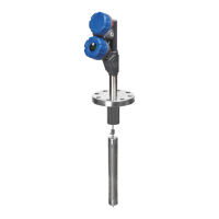
Single Rod: Nozzles do not restrict performance by ensuring the following:
No nozzle is <2" (50 mm) diameter
Ratio of Diameter: Length is 1:1 or greater;
any ratio <1:1 (e.g., a 2" × 6" nozzle = 1:3) may require a Blocking Distance
and/or DIELECTRIC adjustment
No pipe reducers are used
Obstructions
Keep conductive objects away from probe to ensure proper performance
Shock Class ANSI/ISA-S71.03 Class SA1
Vibration Class ANSI/ISA-S71.03 Class VC2