MP7500 Router Installation Manual Version 1.0
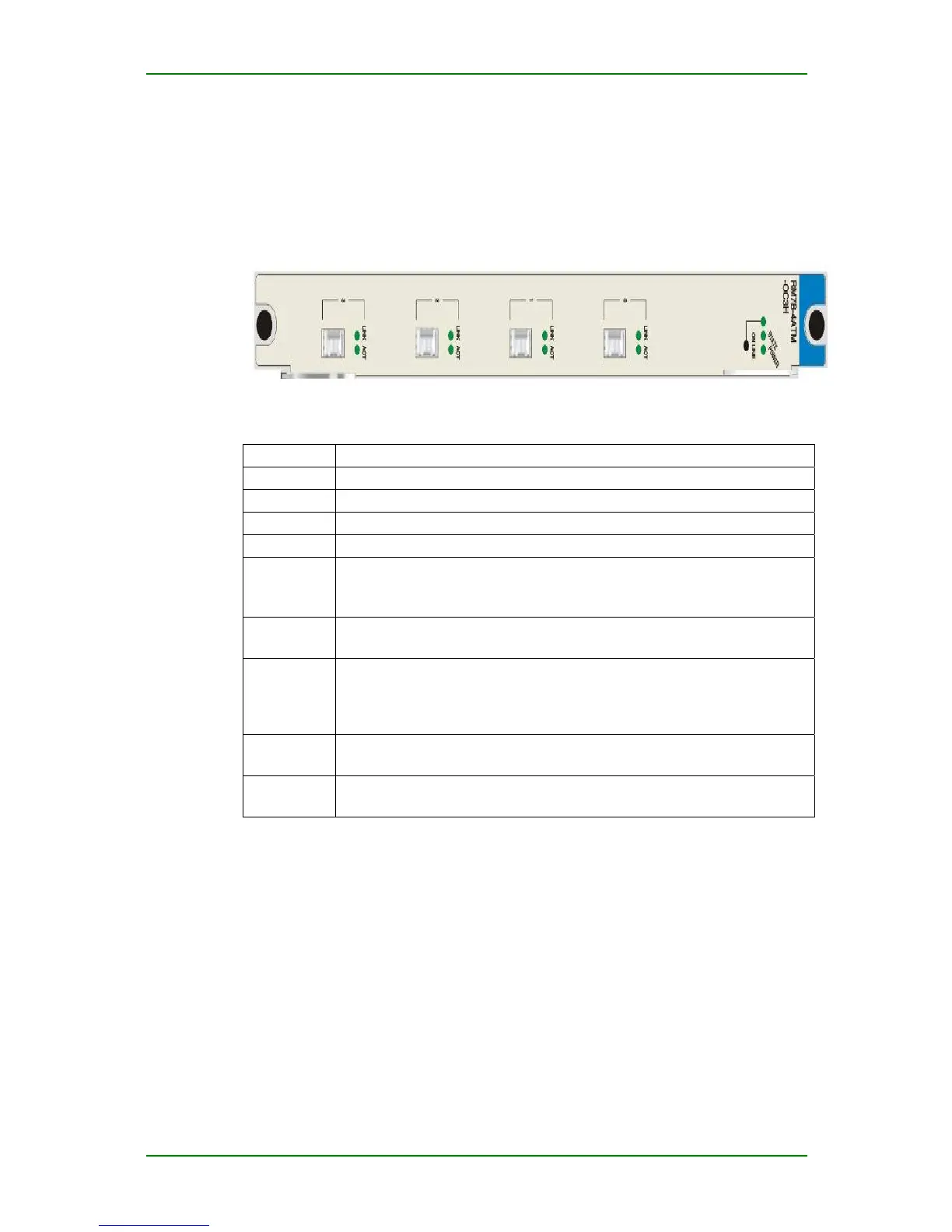
RM7B-4ATM-OC3H Interface Board Panel
and Indicators
RM7B-4ATM-OC3H interface board panel:
RM7B-4ATM-OC3H interface board indicators:
Indicator Description
0 The status of the first port
1 The status of the second port
2 The status of the third port
3 The status of the fourth port
LINK (green
light)
On: Link connected
Off: Link not connected
Flash: The port is configured with local loop and loopback is checked.
ACT
(green light)
Flash: with data receiving and sending
Off: no data receiving and sending
ONLINE
(green light)
On: RM7B-4ATM-OC3H card is in online state and cannot be swapped.
Flash: The system is responding to hot swap processing (flash frequency is
1Hz).
Off: RM7B-4ATM-OC3H card is in offline state and can be swapped.
POWER
(green light)
On: Power normal
Off: power alarm
STATE
(green light)
Off/on: not work normally
Flash: works normally (flash frequency is 1Hz)
RM7B-4ATM-OC3H Interface Board
Connected Cable
RM7B-4ATM-OC3H interface board adopts the fiber with dual LC
connectors.
Maipu Confidential & Proprietary Information Page 20 of 62