MP7500 Router Installation Manual Version 1.0
16-channelized E1 Interface
Board (RM7B-16CE1H)
The 16-channelized E1 interface board provides 16 1984K (31×64Kbps)
multi-timeslots data flow receiving, sending and processing port. For CE1
interface, divide timeslot 1-31 to different groups, and each group works
as one interface after binding.
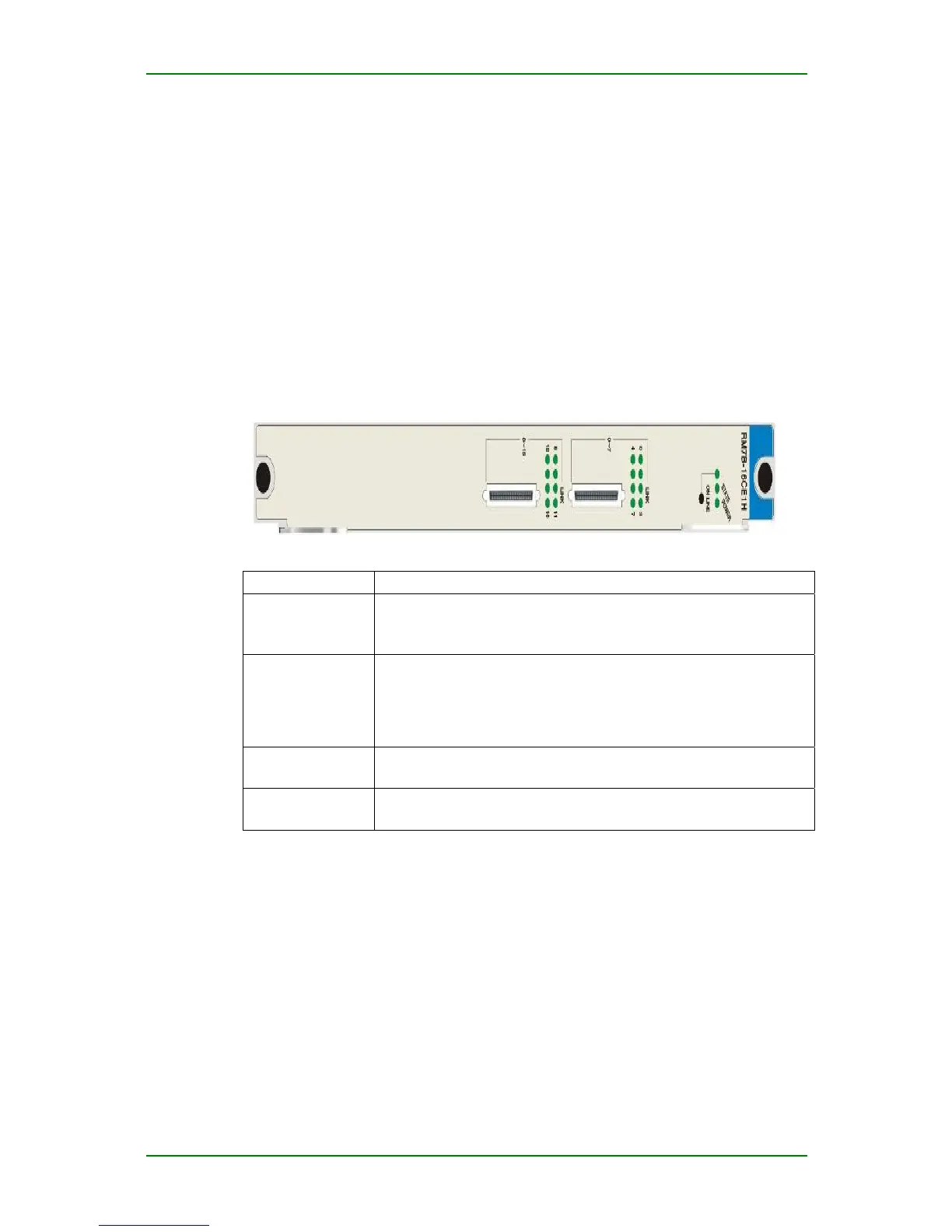
RM7B-16CE1H Interface Board Panel and
Indicators
RM7B-16CE1H interface board panel:
RM7B-16CE1H indicators:
Indicator Description
LINK (0-15)
(green light)
On: Link up
Off: Link down
Flash: Link loopback
ONLINE
(green light)
On: RM7B-16CE1H card is in online state and cannot be
swapped.
Flash: The system is responding to hot swap processing (flash
frequency is 1Hz).
Off: RM7B-16CE1H card is in offline state and can be swapped.
POWER
(green light)
On: Power normal
Off: power alarm
STATE
(green light)
Off/on: not work normally
Flash: works normally (flash frequency is 1Hz)
RM7B-16CE1H Interface Board
Connected Cable
16CE1H interface board adopts special DB40<——> 8×BNC cable to
provide 75Ω unbalance coaxial cable interface.
Maipu Confidential & Proprietary Information Page 25 of 62