CHALLENGERSERIES10‐60KVA PRODUCTDESCRIPTION
AG–SD‐35Rev.No:1Rev.Date:25.09.2013PublicationNo:2 15
2.1GeneralInformation
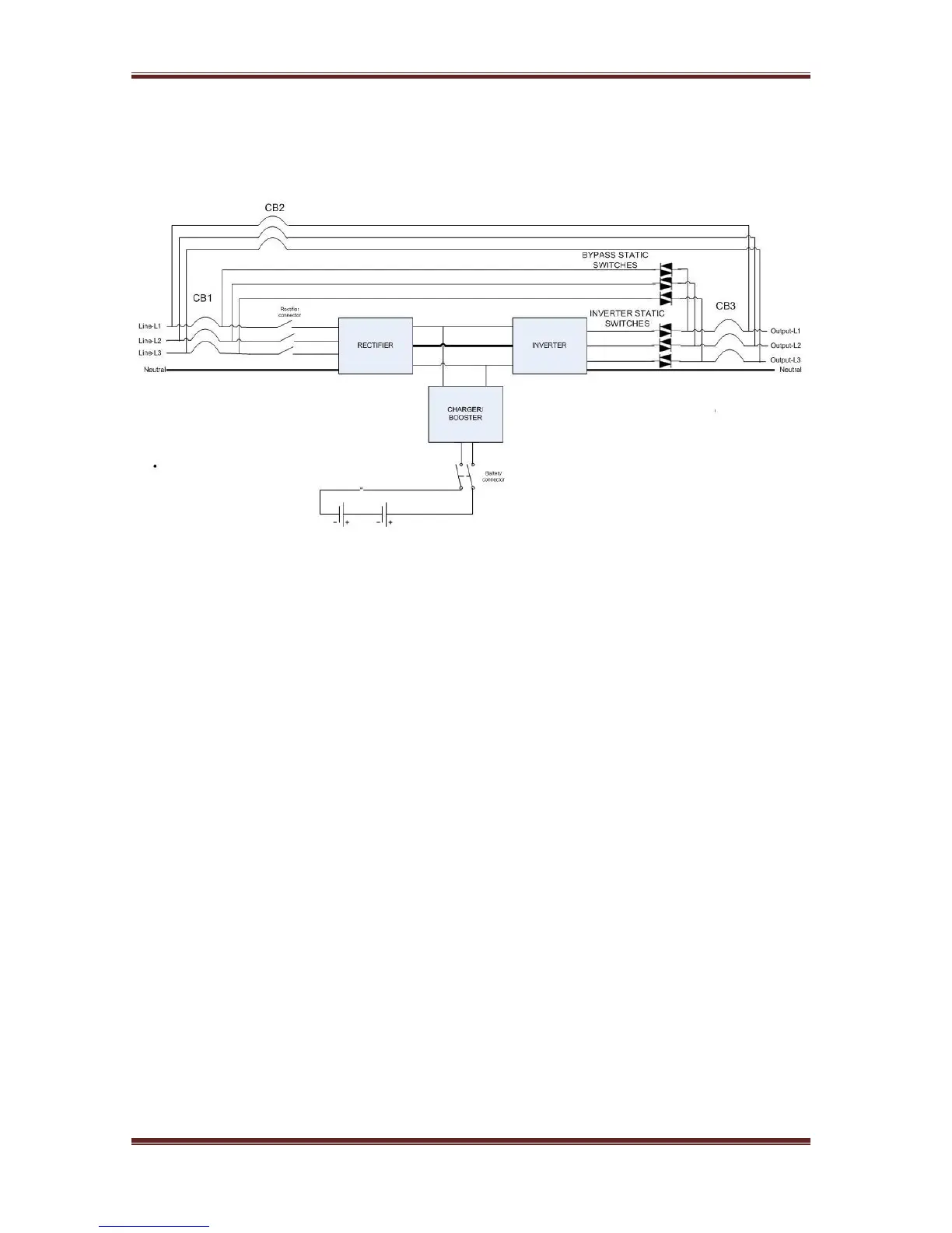
GeneraloperationtopologyofChallenger
®
SeriesUPScanberecognizedasfollows:
TheUPSisconnectedtothemainsvoltagethroughtheCB1breaker.AsDCbusisrampedup,
the rectifier starts to operate and converts the AC mains to DCvoltage.Whenthemains
voltage is not available, the DC/DC booster pumps the battery voltage to the necessary
level.DCDCbusvoltageisthenconvertedtomainssynchronizedACvoltagebytheinverter..
Thisisahighqualityvoltage.GeneratedACpowerisappliedloadsafterstaticsemi‐conductor
switchesandoutput(load)breakers.
2.1.1StaticTransferSwitch
Someblocksarenamedas“staticswitches”ascanbeseenabove. These blocks consist of
inverse parallel connected thyristors . These switches, which areunderthecontrolofthe
mainboard control unit (DSP), provides controlling of supplyingtheloadsthrougheither
mains or inverters.. The loads are supplied through inverter during the normal operating
mode.Therefore,Inverterstaticswitchesareactiveifthereisnoproblemwiththesystem.
Systemprovidestheloadstobefedsmoothandseamlessbymainsorinverter.Inorderto
managehisprocessatminimumrisk,UPSsychronizestheinverteroutputandstatic(mains)
bypassasphaseandfrequency.Therefore,Inverterfrequencycanbeconsideredasmains.It
isthesameasmainsfrequencyaslongasitiswithinfrequencylimit.
UsercanswitchtheUPSbetweenmainsandinverterbyusingfrontpanel.Whiletheloadsare
feddirectlybymainswiththeorderofuser,incaseofeitherpowerofformainsvaluesoutof
tolerances,theUPSwillstarttosupplytheloadsthroughbatterymode.
Iftheuserwants,canprovidemainstofeedloadcontinuouslyby switching on the
maintenance bypass without making adjustment on the front panel. Later on, the user can
maketheinputandoutputswitchfusesshortcircuit.