LEVELUPS SERIES 10-20 KVA PRODUCT DESCRIPTION
AG-SD-83 / Publication Date: 15.09.2014 / Rev. No: 0 / Rev. Date:
2.1 General Information
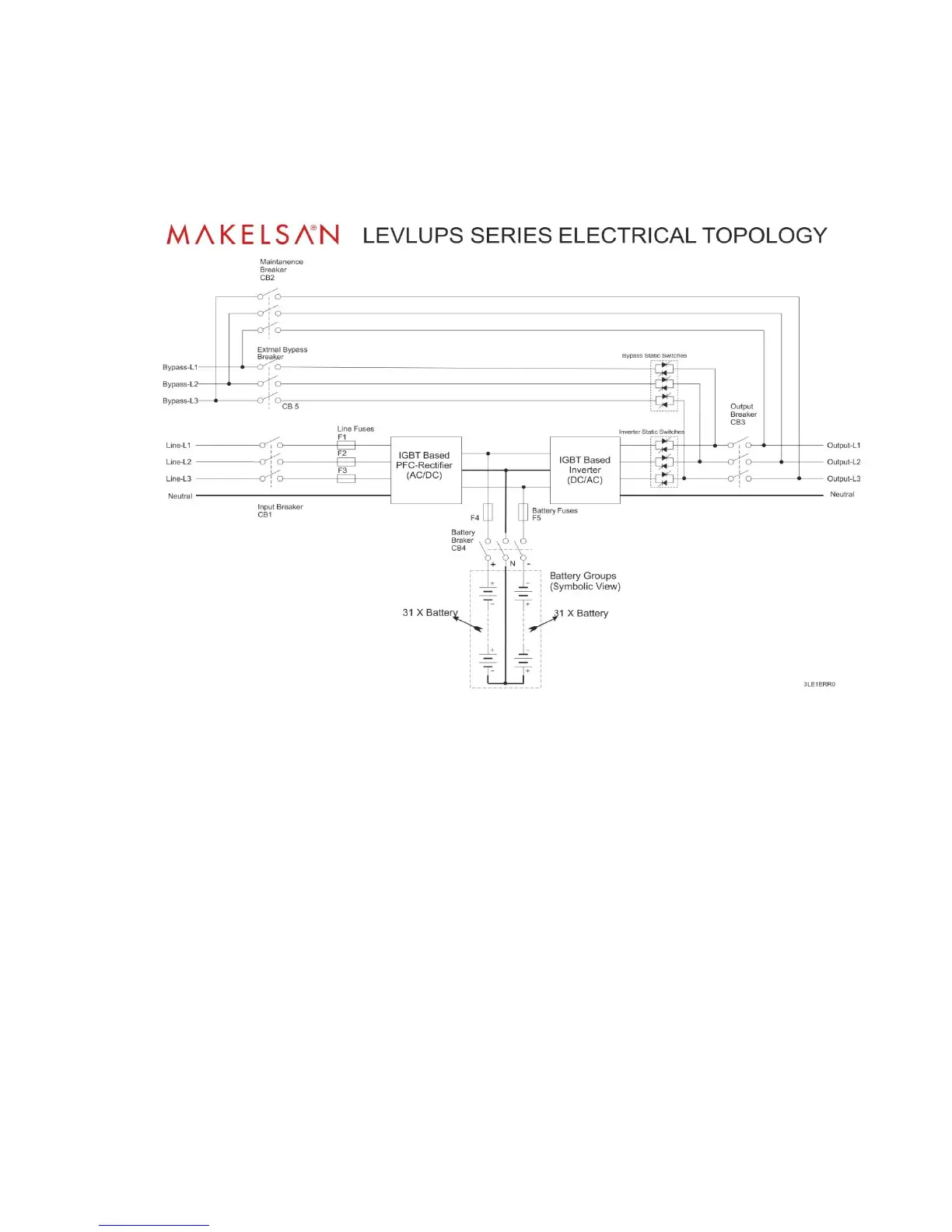
General operation topology of LevelUps Series can be recognized as follows:
The UPS is connected to the mains voltage through the CB1 breaker. As DC bus is ramped up, the
rectifier starts to operate. Rectifier converts the AC mains to DC voltage and charges the
batteries. When the mains voltage is not available, the necessary the DC bus voltage is generated
with use of the battery voltage. DC DC bus voltage is then converted to mains synchronized AC
voltage by the inverter. This is a high quality voltage. Generated AC power is applied to loads
through the static semi-conductor switches and output (load) breakers.
When maintenance or repair is needed, before the Input (CB1) and Output switches (CB3) are
put to the open circuit (OFF) position, the device must be switched to static bypass mode (please
see 4.1.3.2). Consequently the maintenance switch (CB2) is put to the position closed circuit
(ON). After that first Output breaker (CB3), then Input switches (CB1) are turned OFF
respectively.
2.1.1 Static Transfer Switch
Some blocks are named as “static switches” as can be seen above. These blocks consist of inverse
parallel connected thyristors. Controlled by the main board control unit (DSP) these switches
provide feeding of the loads through either mains or inverters. The loads are supplied through