A5A5
11
22
A6A6
22
11
A4A4
11
22
33
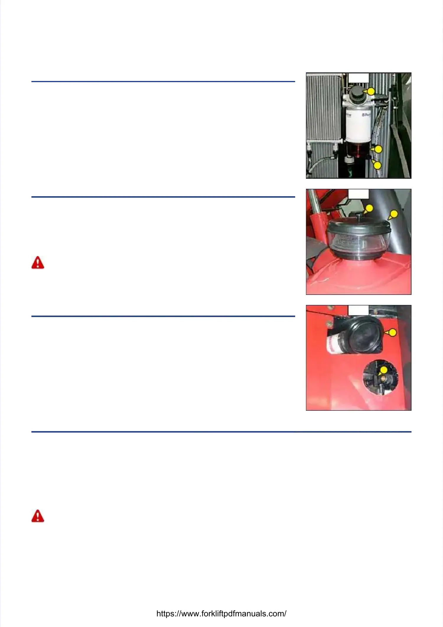
A4 - FUEL PRE-FILTERA4 - FUEL PRE-FILTER
CHECKCHECK
- Open the I.C. engine bonnet.- Open the I.C. engine bonnet.
- Check for the presence of water in the pre-filter bowl 1 (fig. A4) and empty it out if necessary.- Check for the presence of water in the pre-filter bowl 1 (fig. A4) and empty it out if necessary.
-- Place a receptacle under the drain plug 2 (fig. A4) and loosen Place a receptacle under the drain plug 2 (fig. A4) and loosen it in two to three threadit in two to three thread
turns.turns.
- Allow the diesel fuel to flow out until it is free from impurities and water.- Allow the diesel fuel to flow out until it is free from impurities and water.
- Tighten the drain plug.- Tighten the drain plug.
-- Pressurise the circuit with Pressurise the circuit with the hand pump the hand pump 3 (fig A4)3 (fig A4)
A5 - CYCLONIC PREFILTERA5 - CYCLONIC PREFILTER
CLEANCLEAN
The cleaning interval is given as a guide, however the pre-filter must be emptied as soonThe cleaning interval is given as a guide, however the pre-filter must be emptied as soon
as impurities reach the MAXI level on the tank.as impurities reach the MAXI level on the tank.
- Loosen nut 1 (fig. A5), r- Loosen nut 1 (fig. A5), remove cover 2 (fig. A5) and empty emove cover 2 (fig. A5) and empty the tank.the tank.
- Clean the pre-filter unit with a clean dry cloth and reassemble the unit.- Clean the pre-filter unit with a clean dry cloth and reassemble the unit.
When cleaning, take care not to let iWhen cleaning, take care not to let impurities into the dry air mpurities into the dry air filterfilter..
A6 - GEAR BOX OIL LEVELA6 - GEAR BOX OIL LEVEL
CHECKCHECK
Park the lift truck on level grPark the lift truck on level ground with the jib raised, the I.C. engine cold and stopped. Carround with the jib raised, the I.C. engine cold and stopped. Carryy
out the control within 5 out the control within 5 minutes of the I.C. engine being stopped.minutes of the I.C. engine being stopped.
- Remove the plastic cap 1 - Remove the plastic cap 1 (fig. A6).(fig. A6).
- Remove the dipstick 2 (fig. A6).- Remove the dipstick 2 (fig. A6).
- Wipe the dipstick and check the correct level between the two MIN and MAX. marks.- Wipe the dipstick and check the correct level between the two MIN and MAX. marks.
- If necessary, add oil (see: 3 - MAINTENANCE: E3 - GEAR BOX OIL).- If necessary, add oil (see: 3 - MAINTENANCE: E3 - GEAR BOX OIL).
-- Check visually that there is no leakage Check visually that there is no leakage or seepage of oil in the tranor seepage of oil in the transmission.smission.
A7 - TYRES PRESSURE AND WHEEL NUTS TORQUEA7 - TYRES PRESSURE AND WHEEL NUTS TORQUE
CHECKCHECK
- Check the condition of the tyres, - Check the condition of the tyres, to detect cuts, protuberances, wear, etc.to detect cuts, protuberances, wear, etc.
-- Check the torque load of the whCheck the torque load of the wheel nuts. Non compliance with this inseel nuts. Non compliance with this instruction can cause damage and rupture to the wheel boltstruction can cause damage and rupture to the wheel bolts
and distortion to the wheels.and distortion to the wheels.
Wheel nuts tightening torqueWheel nuts tightening torque
• • Front Front tyres: tyres: 630 630 N.m N.m ± ± 15%15%
• • Rear Rear tyres: tyres: 630 630 N.m N.m ± ± 15%15%
- Check and adjust the tyre pr- Check and adjust the tyre pressures if necessaressures if necessary (see: 2 - DESCRIPTION: FRONT AND REAR TYRES).y (see: 2 - DESCRIPTION: FRONT AND REAR TYRES).
Check that the air hose is correctly connected to the tyre valve before inflating and keep all persons at a distance during inflation. Respect theCheck that the air hose is correctly connected to the tyre valve before inflating and keep all persons at a distance during inflation. Respect the
recommended tyre pressures given.recommended tyre pressures given.
NOTE: There is an OPTIONAL wheel toolkit.NOTE: There is an OPTIONAL wheel toolkit.
 Loading...