SET-UP AND INSTALLATION 31000 LUFFING JIB OPERATOR MANUAL
4-30 Published 07-23-15, Control # 078-03
30
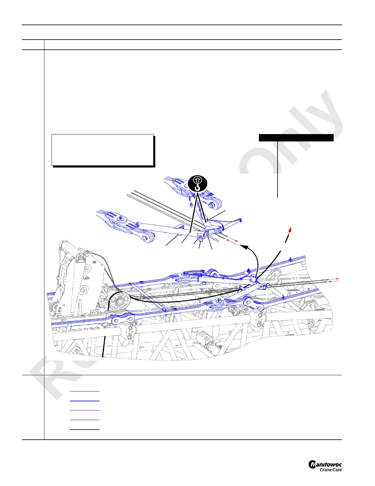
Information below from drawing A19443, Sheet 16 and 17:
• Reposition the Drum 5 wire rope as follows:
- Support the spreader halves (A and B) with lifting slings from the assist crane.
- Remove the pins (C and D) to create and opening between the spreader halves.
- Pass the Drum 5 wire rope (F) through the opening and lay the wire rope on top of the boom sections.
- Close the spreader halves (A and B) and reinstall pins (C and D)
- Disconnect the lifting slings
- IMPORTANT: Be sure to position the Drum 5 wire rope under the roller (G) when the strut is raised.
31
Connect the strut cap to the jib backstay spreader:
•Go to Figure 4-32
if the crane boom length is 55 m (180.5 ft).
•Go to Figure 4-33
if the crane boom length is 60 m (196.9 ft).
•Go to Figure 4-34
if the crane boom length is 65 m (213.3 ft).
•Go to Figure 4-35
if the crane boom length is 70 m (229.7 ft), 75 m (246.1 ft), 80 m (262.5 ft), or 85 m (278.9 ft).
•Go to Figure 4-36
if the crane boom length is 90 m (295.3 ft), 95 m (311.7 ft), 100 m (328.1 ft), or 105 m (344.5
ft).
Step Action
FIGURE 4-31
A
60 m (196.9 ft) boom length
configuration shown.
Item Description
A Left spreader half
B Right spreader half
C Pin with cotter pins (2)
D Pin with cotter pins (2)
E Cylinder rod end
F Drum 5 wire rope
G Roller
H Drum 6 wire rope
Failure to position the Drum 5 wire
rope (F) under the spreader halves (A
and B) will result in structural damage
when the main strut is raised.
E
B
G
D
C
F
H
H
F
 Loading...


