HYDRAULIC SYSTEM 5540F/YB5515 SERVICE MANUAL
4-50 Published 10-21-2010, Control# 198-04
11. Remove four capscrews 1 from mounting flange 3.
These screws were installed with Loctite to hold them in
place.
The screws will require 300 - 400 lb-in (35 - 45 Nm) of
torque to break loose and 100 lb-in (11 Nm) torque to
remove. Do not use an impact wrench on the screws.
This could result in rounded heads or broken sockets.
NOTE: If a torque higher than given above is required to
break the capscrews loose, apply heat according to
the following:
When heated, Loctite partially melts. This reduces
the torque required to remove screw. Use a small
flame propane torch to heat a small area of the
housing where the screws enter. Figure 4-51. Be
careful not to overheat the housing and damage
the motor. Gradually apply torque to the capscrew
with a socket wrench as heat is applied for 8 to 10
seconds. As soon as the screw breaks loose,
remove the heat from the housing. Continue
turning the screw until it is completely removed.
Repeat for other capscrews.
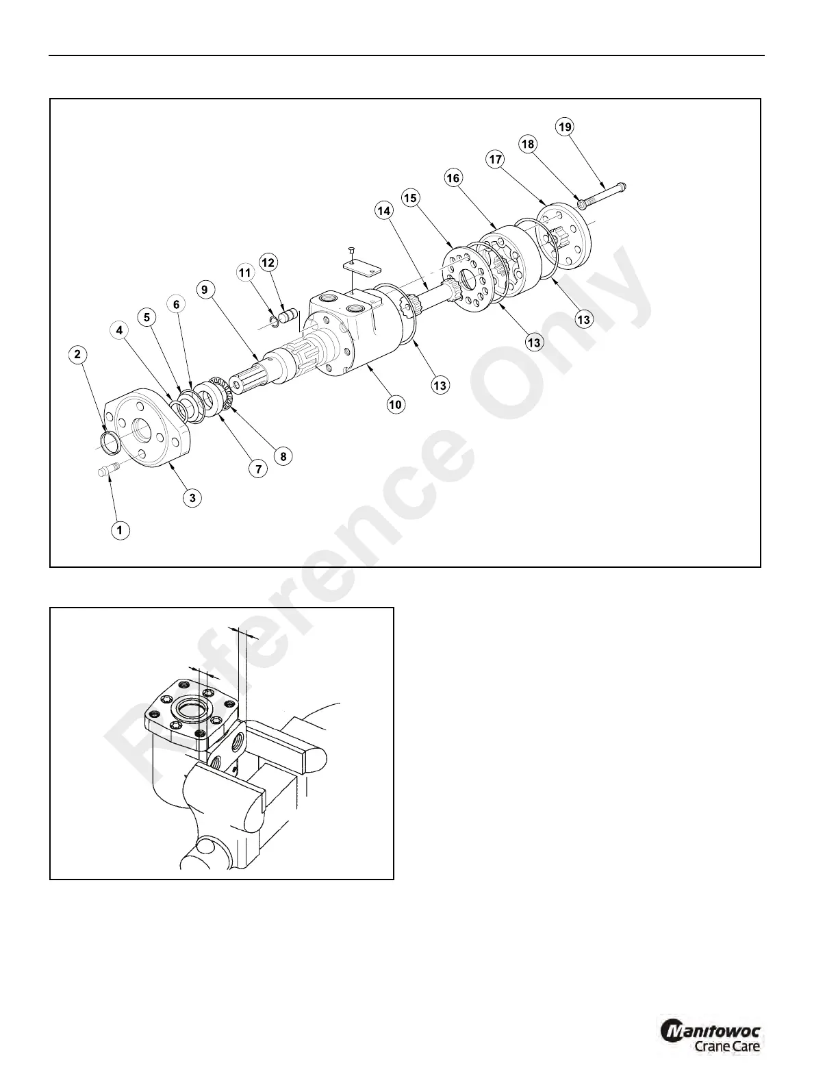
12. Carefully remove flange 3 Figure 4-49 from housing 10.
a0949
FIGURE 4-49
1. Screw (4)
2. Exclusion Seal
3. Mounting Flange
4. Backup Ring *
5. Shaft Pressure Seal *
6. Seal *
7. Bearing Race
8. Thrust Needle Bearing
9. Output Shaft
10. Housing
11. O-Ring
12. Plug
13. Seal (3) *
14. Drive Shaft
15. Spacer Plate
16. Gerotor Set
17. End Cap
18. Seal Washer (7) *
19. Screw (7)
* Included In Seal Kit
Swing Motor
a0764
FIGURE 4-50
1/2” (13 mm)
1/2” (13 mm)
Reference Only

 Loading...


