GROVE Published 10-21-2010, Control# 198-04 4-51
5540F/YB5515 SERVICE MANUAL HYDRAULIC SYSTEM
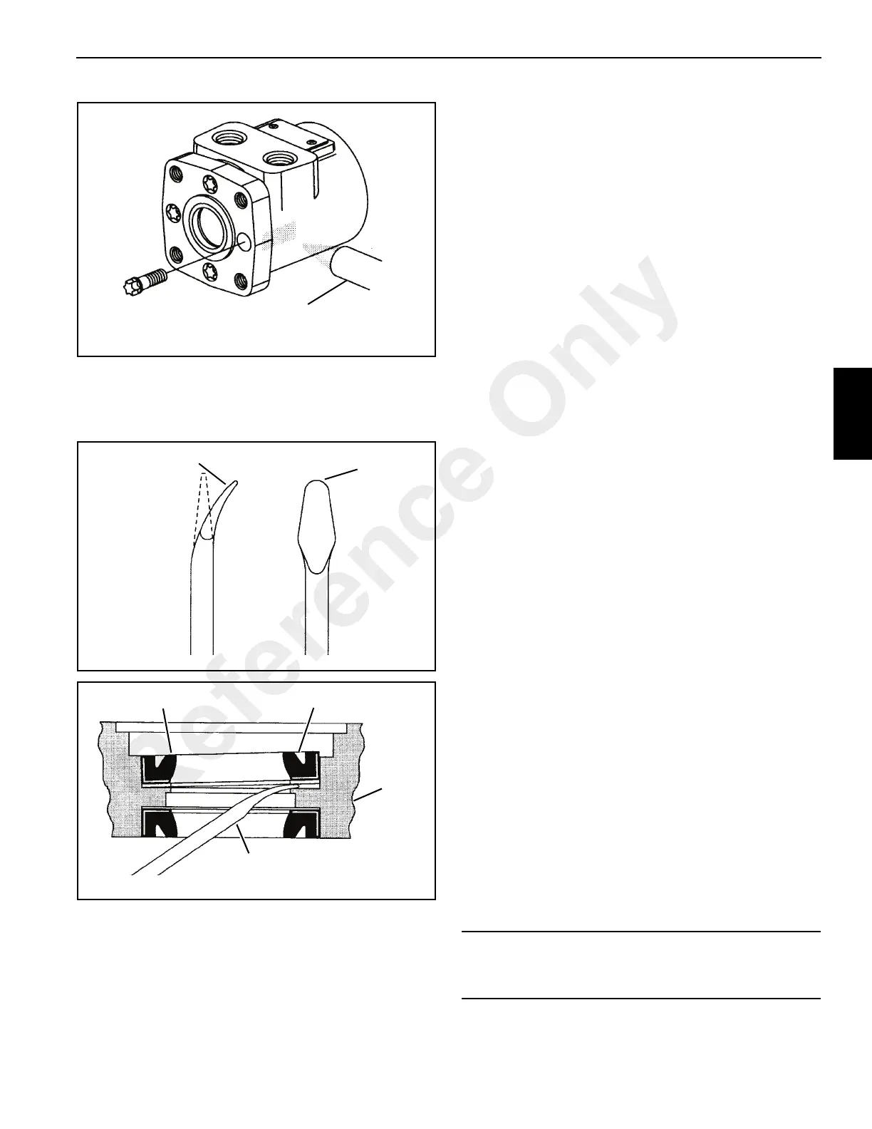
13. Exclusion seal 2, backup ring 4, shaft pressure seal 5
and seal 6 will come off with flange 3. Use the seal
removal tool to remove the exclusion and pressure seals
Figure 4-52 and Figure 4-53.
14. A metal plug 12 Figure 4-49, with o-ring 11, plugs a
machined hole in the housing. It is not necessary to
remove the plug and replace the o-ring unless leakage
occurs around the plug. To remove the plug, insert a
0.187 inch (5 mm) hex key through the port opening and
push it out.
Inspection/Cleaning
Check all mating surfaces. Replace any parts with scratches
or burrs that could cause leakage or damage. Clean all metal
parts in a suitable solvent. Blow dry with air. Do not wipe
parts with a cloth or paper towels, because lint or other
matter could get into the hydraulic system and cause
damage.
Check around the key slot and chamfered area of the shaft
for burrs, nicks or sharp edges that could damage seals
during assembly. Remove nicks or burrs with a hard smooth
stone. Do not file or grind motor parts.
NOTE: Lubricate all seals with petroleum jelly. Use new
seals when assembling the motor. DO NOT
stretch the seals before installing them.
Cleanliness is extremely important in the successful
application of Loctite. Before Loctite can be applied, the parts
should be cleaned as follows:
NOTE: Fully cured Loctite resists most solvents, oils
gasoline and kerosene and is not affected by
cleaning operations. It is not necessary to remove
cured Loctite that is securely bonded in tapped
holes; however, any loose particles of cured Loctite
should be removed.
1. Wash the housing with a suitable solvent to remove oil,
grease and debris. Pay particular attention to the four
tapped holes on the flange end.
2. Blow dry with compressed air. Clean and dry the tapped
holes.
3. Wire brush the screw threads to removed cured Loctite
and other debris. Discard any screws that have
damaged threads or rounded heads.
4. Wash the screws with a non-petroleum base solvent.
Blow dry with compressed air.
Assembly
Shaft End
1. If plug 12 Figure 4-49 was removed, lubricate the new o-
ring 11 and install on the plug. The plug has two o-ring
grooves, but requires only one o-ring in the groove
closest to the end of the plug. Push the plug into the
housing 10 until it is flush with the housing. Be careful
not to damage the o-ring.
2. Lubricate output shaft 9 with hydraulic oil and install the
shaft into housing 10.
a0765
FIGURE 4-51
Heat with a propane
torch to melt Loctite
Capscrew (4)
a0766
FIGURE 4-52
Radius
Bend Tip
Modify
screwdriver as
shown.
Remove all
burrs
a0767
FIGURE 4-53
Mounting
Flange
Seal Tool
Pressure Seal Exclusion Seal
CAUTION
Do not permit oil to get into the four tapped holes of
housing 10.
Reference Only

 Loading...


