GROVE Published 10-21-2010, Control# 198-04 4-53
5540F/YB5515 SERVICE MANUAL HYDRAULIC SYSTEM
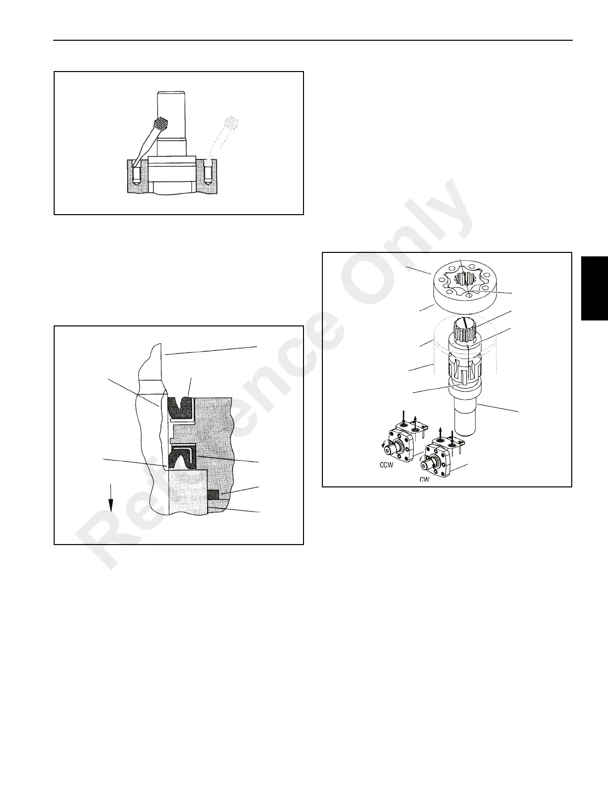
10. Before installing the flange and seal assembly over shaft
9 Figure 4-49, place a protective sleeve or bullet over
the shaft. Then lubricate the space between exclusion
seal 2 and pressure seal 5, as well as the lips of both
seals Figure 4-57.
Install flange. Rotate flange slowly while pushing down
over the shaft. Be careful not to invert or damage the
seals.
11. After removing the protective sleeve or bullet, clamp the
motor in a vise. Make sure the shaft cannot fall out.
Install dry screws and alternately torque them
immediately to 250 lb-in. (28 Nm). If you use primer,
allow to cure for 10 to 15 minutes. Without primer, allow
6 hours curing before subjecting the motor to high torque
reversals.
Gerotor End
12. Reposition the motor in the vise with gerotor end up.
Clamp across the ports. Do not clamp on side of
housing.
NOTE: To aid installation of seals, apply a light coat of
clean petroleum jelly to seals. Do not stretch the
seals before installing them in a groove.
13. Pour approximately 1 ounce (35 mm) of clean hydraulic
oil in the output shaft cavity.
14. Install o-ring 13 Figure 4-49 in the housing groove. Avoid
twisting the seal.
Timing Procedure
15. Install drive shaft 14 Figure 4-49. Use a felt tip pen to
mark one drive tooth. Align this mark with the timing dot
on the output shaft Figure 4-58.
NOTE: If drive shaft 14 is not symmetrical, install larger
splined end into output shaft 9.
16. Install spacer plate 15.
17. Install seal 13 in gerotor seal groove. Carefully place
gerotor on spacer plate, seal side toward the spacer
plate. Align any star point with tooth marked on drive
shaft Figure 4-58.
18. Rotate gerotor 16 to line up with bolt holes. Be careful
not to disengage star from drive or disturb the gerotor
seal.
19. Install seal 13 in end cap 17. Carefully place the end cap
on gerotor 16.
20. Install capscrews 19 and seal washers 18 in end cap 17.
Tighten the capscrews to 40 lb-in. (7.4 Nm). Make sure
the seal washers are properly seated. Then, tighten the
capscrews to a torque of 235-250 lb-in. (27-29 Nm) in
the sequence shown Figure 4-59.
a0770
FIGURE 4-56
Apply 3 or 4
drops in
each hole
Place tip of
applicator at top of
threaded portion
a0771
FIGURE 4-57
Output
Shaft
Apply
petroleum jelly
across this
area (See
step 10).
This lip to
face
inward
Extrusion Seal
(lip face outward)
Pressure
Seal
Seal
Bearing
Race
Interior
of
Motor
a0772
FIGURE 4-58
Output
Shaft
Spacer Plate
Gerotor Seal
(this side)
Gerotor
Housing
Forward
Valving Slot
Timing Dot
Drive Shaft
Star Point
Reference Only

 Loading...


