GROVE Published 10-21-2010, Control# 198-04 7-41
5540F/YB5515 SERVICE MANUAL TRANSMISSION AND TORQUE CONVERTER
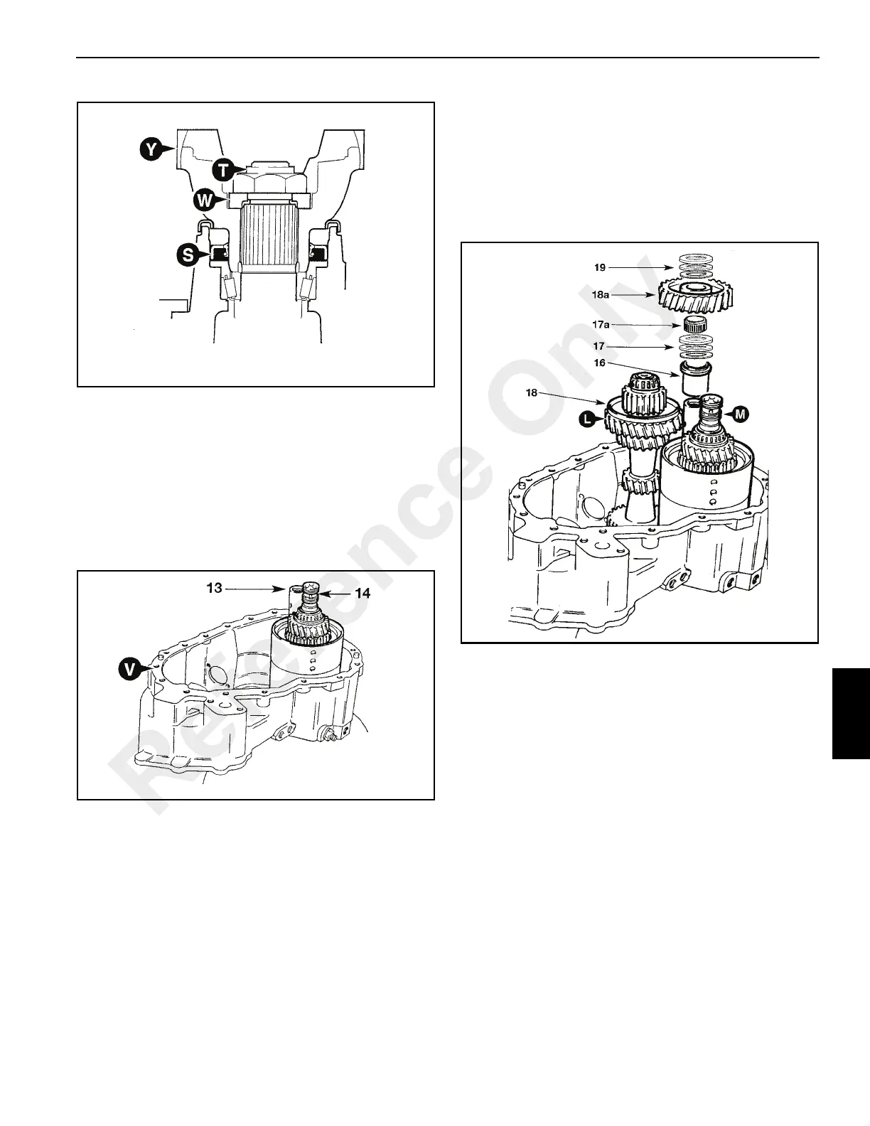
13. Press idler gear spindle 13 (Figure 7-50) into front
casing.
NOTE: Before proceeding further, make sure that the 13
shaft front bearing outer cups are correctly located
inside the casing V.
14. Grease forward/reverse shaft front bearing 14, then
carefully lower the reverser unit into casing. Install the
shaft sealing rings and coat with grease. See Reverser
Unit, Piston Ring Seals - Fitting Procedure.
15. Coat mainshaft output end bearing with Mobil HP222
Grease and place mainshaft L (Figure 7-51) in position,
alongside the reverser unit assembly M.
16. Install idler gear spacer 16.
17. Install thrust washers and bearing assembly 17.
Lubricate and fit the needle roller bearing 17a.
18. Install synchro cone to 3rd gear 18 (mainshaft L). Fit the
idler gear 18a to the spindle while tilting mainshaft L to
one side.
19. Fit thrust washers and bearing assembly 19.
20. Coat front end bearing 20 (Figure 7-52) of layshaft with
Mobil HP222 Grease, and carefully lower layshaft into
position.
21. If re-using synchro assembly 21 install the parts in their
original positions.
22. Using a suitable wire support locate interlock plunger 22
into its bore. A coat of grease will hold the plunger in
position. If required, access is; available via a V4 BSP
side drilling.
Reference Only

 Loading...


