TRANSMISSION AND TORQUE CONVERTER 5540F/YB5515 SERVICE MANUAL
7-42 Published 10-21-2010, Control# 198-04
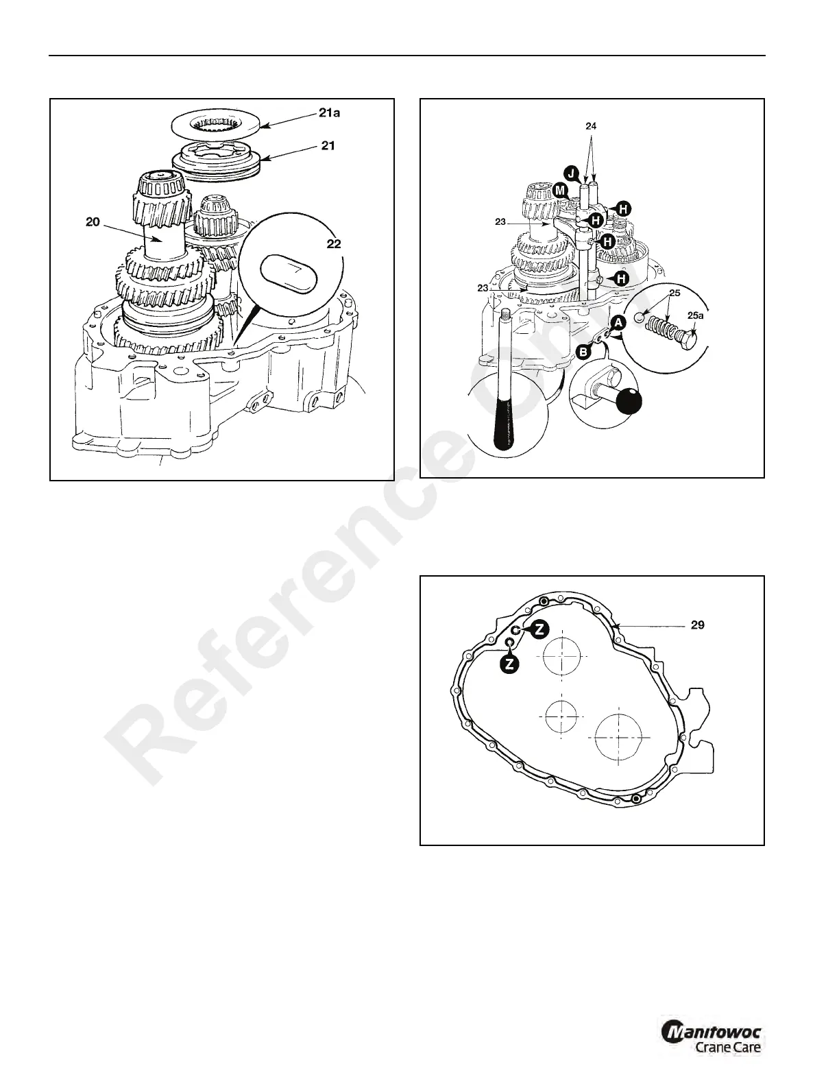
23. Install selector forks 23 (Figure 7-53) into position.
24. Slide selector rods 24 into position, taking care not to
dislodge the interlock plunger. Apply Loctite 242 to
selector fork retaining screws H, and tighten to 26 Ib ft
(35 Nm).
25. Install 1st gear selector detent ball and spring at position
A. Apply Loctite 242 to the detent plug 25a, screw in and
tighten.
26. Temporarily install the 3rd and 4th gear selector detent
assembly at position B, do not apply sealant to the plug
at this time.
27. Check that each gear engages fully, and that the
interlock plunger prevents simultaneous engagement of
2 ratios.
28. Remove the 3rd and 4th gear selector detent assembly
from position B. Lift the selector rod J to select 4th gear.
With 4th gear selected, temporarily lock the rod in
position by screwing in service tool 892/01077 at B.
Temporarily fit service tool 892/01078 to the torque
converter end of mainshaft M. If the tool is not available
a suitable M8 bolt approximately (4 in) long can be used.
29. Apply a bead of Loctite 574 Multi gasket (Figure 7-54) to
mating face of casing. Insert O-rings. Smear grease
onto forward/reverse shaft ring seals, and apply Mobil
HP222 Grease to bearings prior to fitting the output end
casing.
NOTE: Make sure that the forward/reverse shaft ring seals
are in good condition before fitting the output end
casing.
30. Make sure that the 3 bearing outer cups C, (Figure 7-55)
are correctly located; note that 2 cups locate inside the
casing and 1 locates in the centre of the output shaft
transfer gear G. Carefully lower rear casing into position.
Note that the reverser unit shaft engages with the casing
Reference Only

 Loading...


