GROVE Published 10-21-2010, Control# 198-04 7-43
5540F/YB5515 SERVICE MANUAL TRANSMISSION AND TORQUE CONVERTER
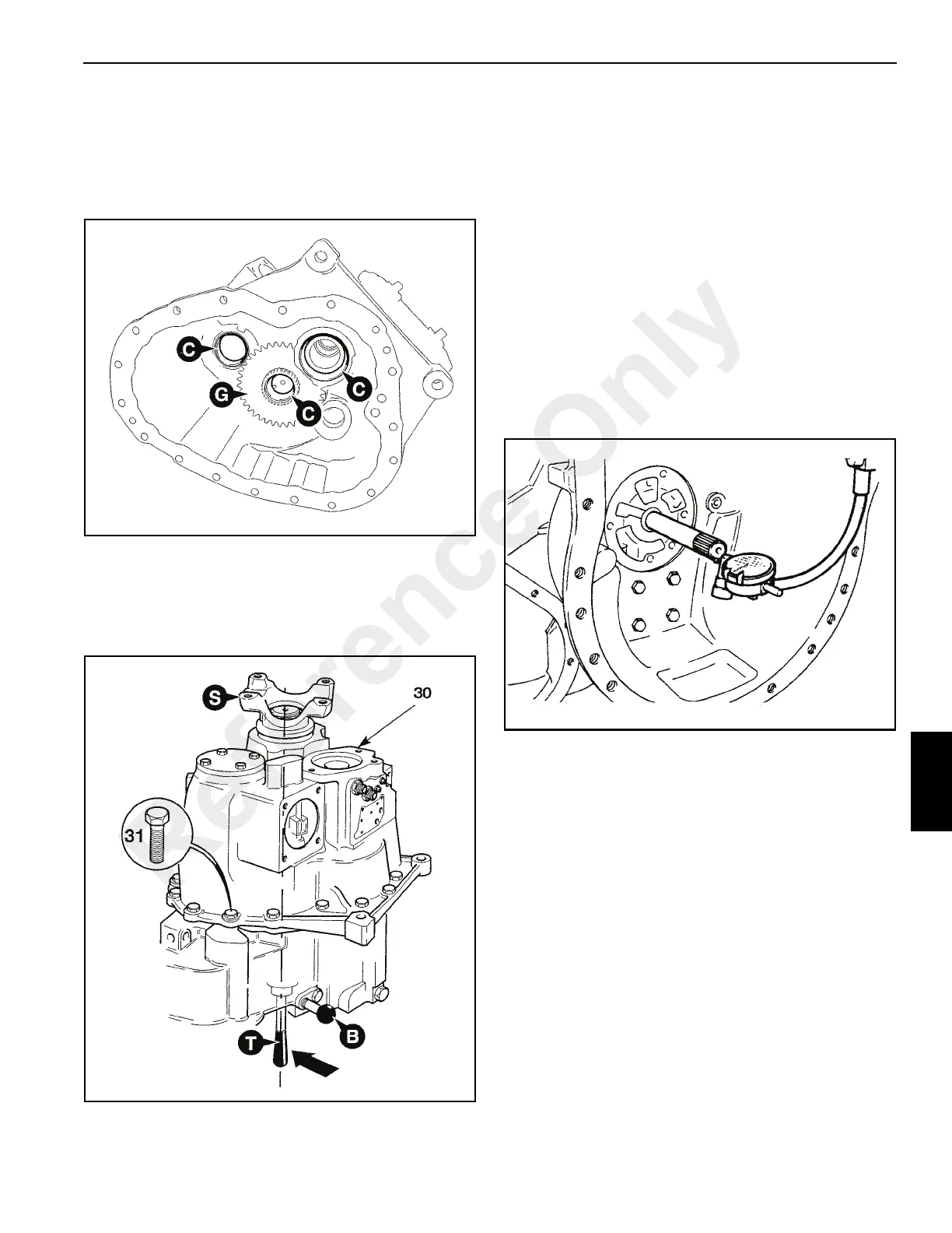
first, followed by 3rd/4th gear selector rod. To ensure
that the mainshaft locates with the output shaft it will be
necessary to push on tool T to keep the shaft correctly
aligned. Rotate the output shaft S back and forth to
engage the gears on the layshaft. Do not use excessive
force when fitting the casing.
31. Apply Loctite 242 to bolts 31, (Figure 7-56) and torque to
42 lb ft (57 Nm).
32. Remove service tool at position B. Install the detent ball
and spring. Apply Loctite 242 to selector detent plug,
install and tighten.
33. End Float Checking - Reverser Unit (Figure 7-57)
Measure end float of forward/reverse shaft which should be
0.0004 to 0.006 in (0.01 to 0.16 mm).
NOTE: Rotate shaft while measuring to seat bearings fully.
Position pointer of dial test indicator (DTI) on the
chamfer of the shaft, not the end face. This will
ensure a constant reading is given.
The forward/reverse shaft and its associated components
are manufactured using a 'Set-right' system. Provided
components are assembled correctly, the end float will be
within the limits given above.
If there is no float, or too much end float, separate the
casings and check that the bearings inner and outer cups are
fitted correctly. If the forward/reverse shaft and clutch
assemblies have been dismantled check that the assembly
has been carried out correctly.
34. End Float Setting - Mainshaft (See Figure 7-55 and
Figure 7-56)
If the mainshaft, output shaft and/or associated bearings
have been renewed, the shaft end float must be reset.
a. Remove the torque converter housing and position
the gearbox to gain access to setting ring A.
b. Using service tool 892/01079 tighten the setting ring
to 18.4 Ib ft (25 Nm) whilst at the same time rotating
the shaft via the output yoke (a gear must be
engaged). Do not over tighten the ring.
Overtightening will damage the bearings.
c. Undo the ring a small amount to obtain a shaft end
float of 0.001 to 0.003 in (0.03 to 0.08 mm). To
measure the end float screw in a bolt at the
threaded hole in the end of the shaft. Set up a DTI
with the probe on the chamfer of the shaft. Zero the
DTI. Rotate the shaft and at the same time pull up
on the bolt, noting the reading on the DTI. Screw the
ring in or out until the end float is correct.
Reference Only

 Loading...


