GROVE Published 10-21-2010, Control# 198-04 7-47
5540F/YB5515 SERVICE MANUAL TRANSMISSION AND TORQUE CONVERTER
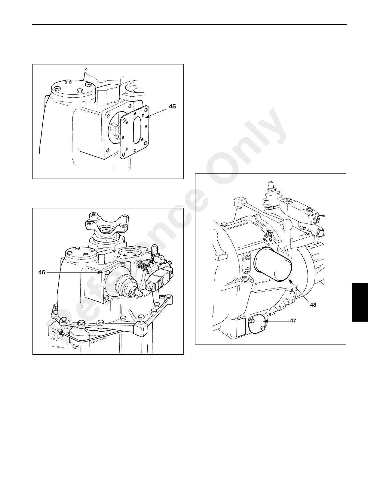
45. Locate a new gasket (not shown) on the casing followed
by the gear lever turret baffle plate (Figure 7-68). Make
sure the plate is the correct way round.
46. Locate a second gasket and then fit the turret assembly
46 (Figure 7-69). Apply Loctite 242 to mounting bolts
and tighten to 42 Ib ft (56 Nm). Check for gear selection.
NOTE: It is recommended that a 75 micron (0.075mm)
service suction strainer (892/00970) is fitted to
clean the system after a major overhaul.
Remove the service strainer and fit a production
strainer after the first 100 hours operation. Renew
the oil.
47. Using a new gasket, install suction strainer 47
(Figure 7-70). Apply Loctite 242 to bolts and tighten to 7
Ib ft (10 Nm).
48. Install a new filter 48.
49. Install dipstick/oil filler tube (not shown) as follows:
a. Fit nut to tube followed by seal.
b. Insert tube fully down bore in casing. Engage nut
and tighten down loosely onto seal.
c. Tighten nut fully after tube has been correctly
phased.
See Hydraulic 2/4-Wheel Drive Unit for 4WD clutch
disassembly and assembly procedures.
50. Fit a new sealing ring 50a (Figure 7-71) to the pump
drive shaft. Insert the pump drive shaft followed by
bearing 50b and circlip 50c.
51. Carefully locate the splined shaft of the pump into the
gearbox. Apply Loctite 242 to the threads of the two
fixing bolts and secure the pump flange to the gearbox
mounting face.
Reference Only

 Loading...


