GROVE Published 10-21-2010, Control# 198-04 8-15
5540F/YB5515 SERVICE MANUAL AXLES/DRIVE SHAFTS/WHEELS AND TIRES
Example:
Dimensions in Millimeters
Dimension A 0.25
Add to depth +30.01
Total 30.26
Add dimension B, if positive.
(Subtract if negative) +0.01
Total 30.27
Add dimension C if negative.
Subtract if positive (+) -0.01
Total 30.28
Standard Value 31.19
Less Calculated total
from above -30.28
Shim Thickness 0.91
Crownwheel and Pinion Adjustment
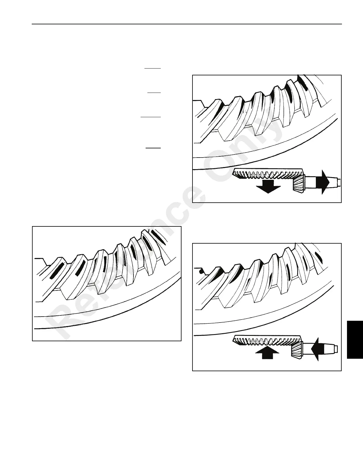
Meshing of the gears should be checked by marking three of
the pinion teeth with engineers marking compound and
rotating the pinion.
The marking will then be transferred to the crown wheel
teeth.
Correct teeth marking Figure 8-28
Pinion too deeply in mesh Figure 8-29
Decrease the shim thickness between the pinion inner
bearing cup and the axle casing. Move the crown wheel
towards the pinion to correct the backlash.
Pinion too far out of mesh Figure 8-30.
Increase the shim thickness between the pinion inner
bearing and the axle casing. Move the crownwheel away
from the pinion to correct the backlash.
Reference Only

 Loading...


