GROVE Published 10-21-2010, Control# 198-04 8-17
5540F/YB5515 SERVICE MANUAL AXLES/DRIVE SHAFTS/WHEELS AND TIRES
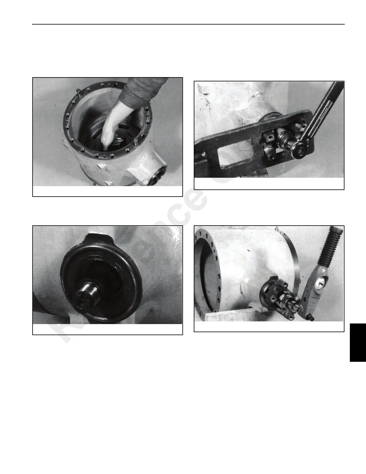
5. Insert the pinion into its bore Figure 8-35. Before
inserting, ensure that the pinion matches the
crownwheel. The code numbers etched on the pinion
end face and the crownwheel perimeter should be the
same.
6. Install the outer bearing cone Figure 8-36 and the seal.
Pack grease between the lips of the seal before
installing.
7. Install the drive coupling yoke and secure it with a new
stake nut and washer.
Hold the yoke Figure 8-37 with the drive coupling
spanner. Tighten the stake nut until end float is almost
zero, then check the seal drag torque. It should be
between 3.5 to 8.9 lb-in. (0,40 to 1,0 Nm).
Continue to tighten the stake nut to achieve the correct
rolling torque as described in Step 8. If the nut is
overtightened, the collapsible spacer must be replaced.
8. Measure the rolling torque Figure 8-38, which should be
1.3 to 2.1 lb-ft (1.7 to 2.8 Nm) excluding seal drag. When
the torque is correct, stake the nut to the pinion shaft
using a square-ended staking tool.
9. If both brake piston housings were removed, install one
at the opposite end of the crownwheel Figure 8-39,
using the procedure in Step 10. Then install the
crownwheel/ differential assembly into the drive head.
Reference Only

 Loading...


