OPERATING CONTROLS AND PROCEDURES RT530E-2 OPERATOR’S MANUAL
3-6 Published 5-3-2016, Control # 555-02
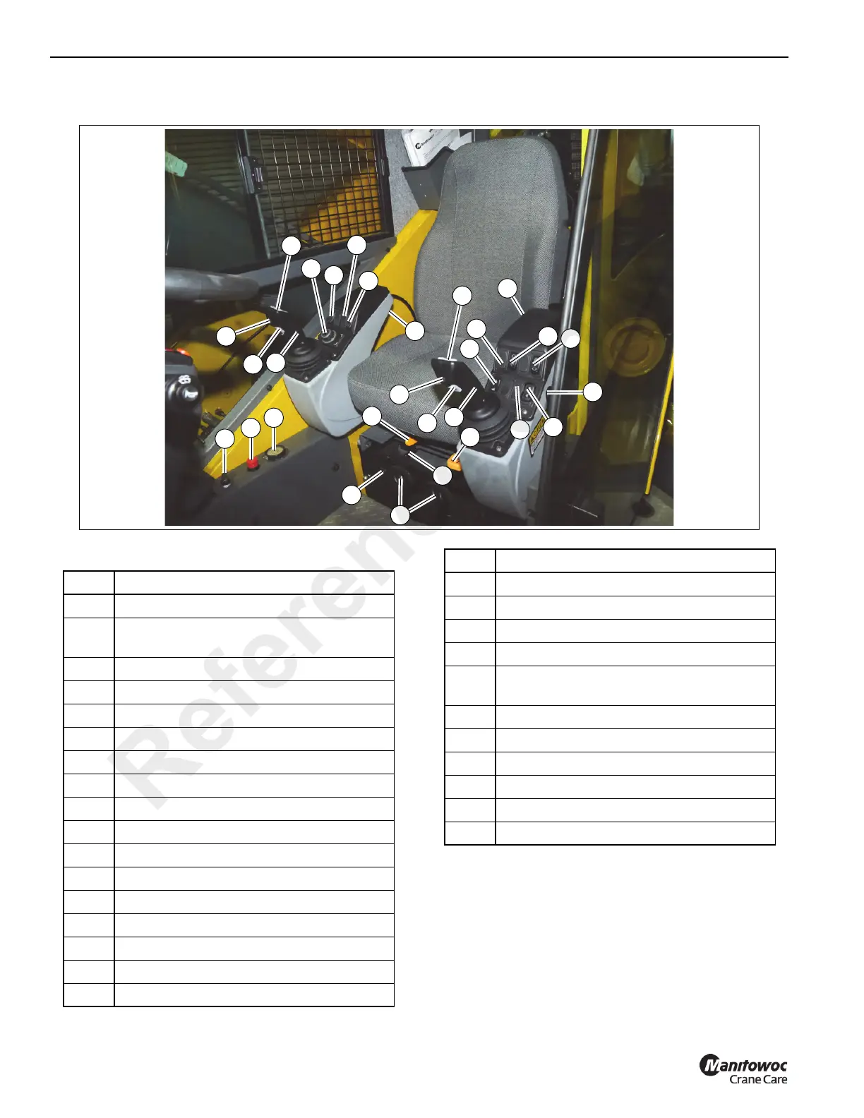
CONTROL SEAT ASSEMBLY
Figure 3-5 Item Numbers
Boom Lift/Main Hoist Control Lever (Dual
Axis)
The Boom Lift/Main Hoist Control Lever (1) (Figure 3-5) is
located on the right armrest. The controller, when pushed to
the right lowers the boom, or pushed left raises the boom.
When used for main hoist, the controller, when pushed
forward lowers the cable, or pulled back raises the cable.
FIGURE 3-5
8044-2
5
3
9
6
26
16
13
18
12
15
14
17
17
19
21
20
7
1
2
8
10
11
23
22
24
25
23
22
4
Item Description
1
Boom Lift/Main Hoist Control Lever
2
Swing/Telescope or Swing/Auxiliary Hoist
Control Lever
3 Main Hoist Enable Switch
4 Boom Up Bypass
(Optional)
5 Boom Lift Function Enable Switch
6 Jog Dial
7
Outrigger Function Enable Switch
8
Differential Lock On/Off (Optional)
9 Rear Steer Switch
10 Auxiliary Hoist Enable Switch (Optional)
11 Boom Telescope Enable Switch
12 Swing Enable Switch
13 Seat Slide Lever
14 AC/Heater Climate Unit
15 AC/Heater Vents
16 Seat Frame Slide Lever
17 Armrest Adjustment Button(s) (Underside)
18 Seat Height Adjustment Lever
19 RCL Bypass Switch
20 Emergency Stop Switch
21 Level Indicator
22
Deadman Switches (Optional) (Dual Axis
Control Levers only)
23 Hoist Speed Toggle Switches
24 Horn
25
Free Swing Button
26
Cab Door Release Lever
27 Hoist Rotation Indicators (Not Shown)
28 Seat Switch (Not Shown)
Item Description
Reference Only

 Loading...


