HYDRAULIC SYSTEM RT765E-2 SERVICE MANUAL
2-70
Published 9-04-2014, Control # 422-08
1. If removed, install the holding valve. Refer to Holding
Valve, page 2-45 in this section.
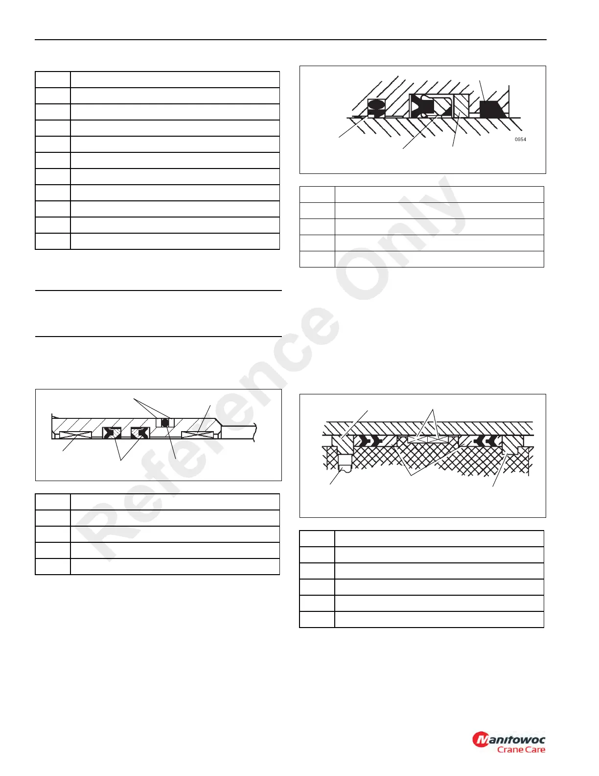
2. Install the O-ring and backup rings on the outside of the
seal retainer and the deep Z rod seals and wear rings in
the inside of the seal retainer Figure 2-40.
3. Slide the seal retainer onto the inner rod.
4. Install the guide lock ring onto the inner rod and slide the
inner rod and seal retainer into the outer rod.
5. Install the wiper ring, backup ring, deep Z rod seal, buffer
seal assembly, and wear rings into the inside of the
cylinder head Figure 2-41.
6. Slide the spacer and head onto the outer rod.
7. Install the O-rings and backup rings on the inside of the
piston.
NOTE: Use a new self-locking soft-tip setscrew.
8. Screw the piston onto the outer rod and secure with
setscrew.
9. Install the guide lock rings, hydrolock seal assemblies
Figure 2-42 and wear rings on the outside of the piston.
10. Install the wear ring to the outside of the spacer.
11. Install the O-ring and backup ring on the outside of the
head.
12. Install the backup ring and O-ring on the outside of the
inner rod end.
Item Description
27 Capscrew
28 Washer
29 Capscrew
30 Washer
31 O-ring
32 Backup Ring
33 Dowel Pin
34 Seal
35 Counterbalance Valve
36 Wear Ring
CAUTION
Avoid scratching or damaging the grooved and gland
surfaces or the seals and rings.
Item Description
1 Wear Ring
2 Rod Seal
3O-ring
4 Backup Ring
Item Description
1 Buffer Seal
2 Rod Seal
3 Backup Ring
4 Wiper Ring
Item Description
1 Setscrew
2 Hydro-lock Seals
3 Backup Ring
4 Guidelock Ring
5 Wear Ring
Reference Only
 Loading...


