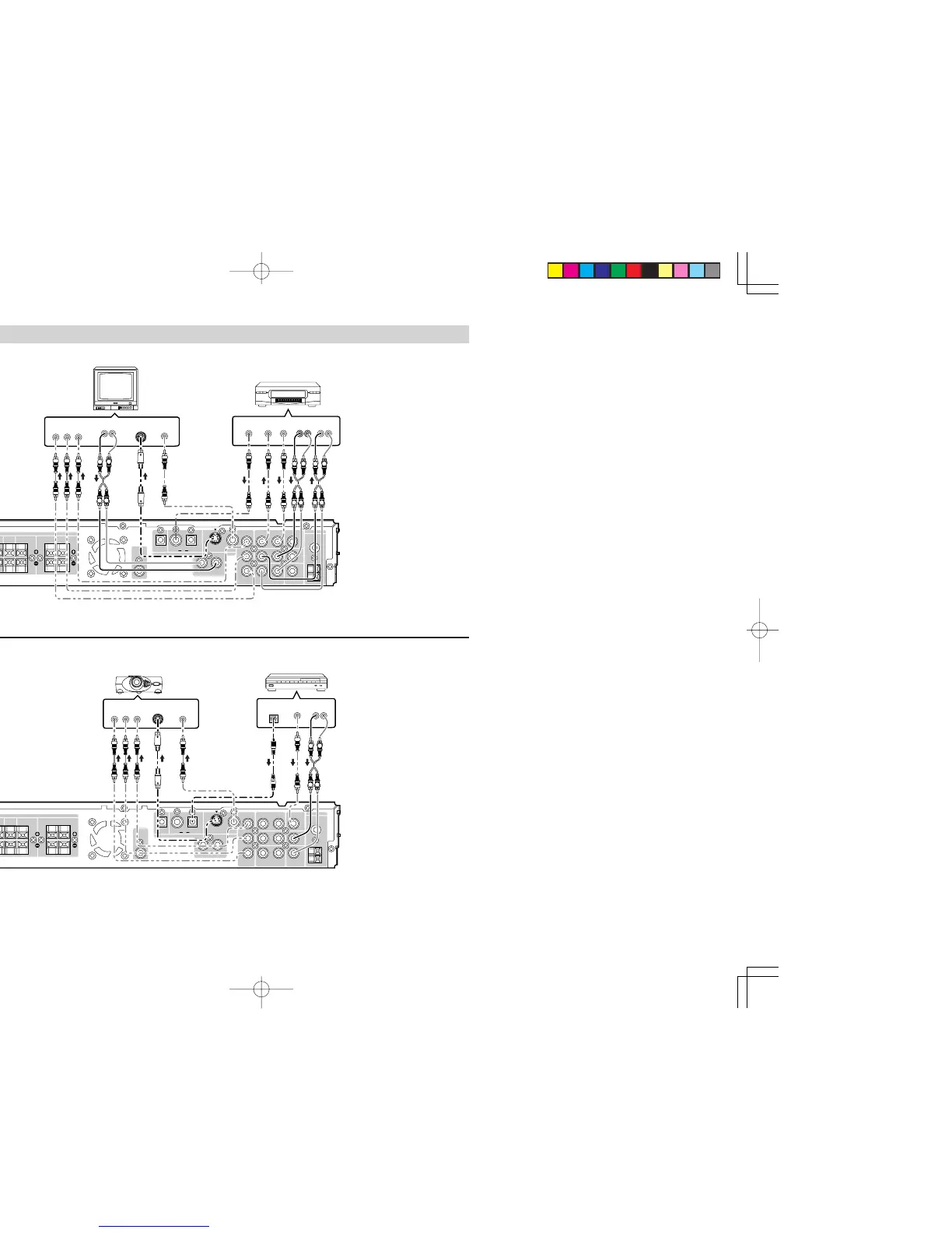
CONNECTING VIDEO COMPONENTS
VIDEO, S-VIDEO, COMPONENT
There are 3 types of video jacks on the rear panel.
VIDEO jack
The video signal for the VIDEO jacks is the
conventional composite video signal.
S-VIDEO jack (DVD mode only)
The video signal is separated into luminance (Y) and
color (C) signals for the S-VIDEO jack. The S-VIDEO
signals enables high-quality color reproduction. If
your video component has an S-VIDEO output, we
recommend to use it. Connect the S-VIDEO output
jack on your video component to the S-VIDEO input
jack on this unit.
Component jack (DVD mode only)
Make component video connections to a TV or
monitor with component inputs to produce higher
quality video images. Use a component video cable
or 3 video cords to connect the component video
out jacks on the this unit to the monitor.
Notes:
• Be sure to connect the left and right audio
channels properly.
Red connectors are for the R (right) channel,
and white connectors are the for L (left) channel.
• Be sure to connect the inputs and outputs of
the video signals properly.
• If you connect the S-VIDEO or component
signal to the S-VIDEO or component jack on
this unit, it is not necessary to connect the
conventional video signal to the VIDEO
(composite) jack. If you use both video inputs,
this unit gives priority to the S-VIDEO signal.
• Each type of video jack works independently.
Signals input to the VIDEO (composite) and
S-VIDEO jacks or component are output to
the corresponding VIDEO (composite) and S-
VIDEO or component jacks, respectively.
• You may need to select the video output
mode from setup menu. Refer to the setup
menu operation.
• There is no Dolby Digital RF input jack.
Please use an external RF demodulator with a
Dolby Digital decoder to connect a video disc
player which has a Dolby Digital RF output
jack to the digital input jack on this unit.
•
If you want to out the analog audio signal from
VCR audio output terminal via FUNCTION
button of ER2500 from digital source (include
the build in DVD player), recommend to select
STEREO surround mode with 2 speakers
setting (Front speaker only).
Video Projector
Satellite Tuner
VCR
TV