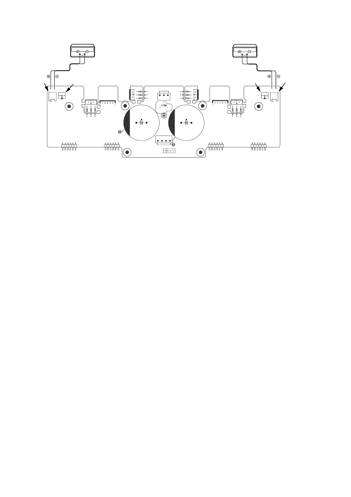
Idling Current Adjustment
1. After DC Offset Voltage Adjustment is completed, adjust the Idling Current with the variable resistor
V7001
and
V7002
on the PCB
P2
(
8U-110150-2
).
2. Turn off the power.
3.
"+"
of Connect Digital Voltage is connected to the No. 1 pin and connected
"–"
to No. 2 pin of
N7007
.
4.
"+"
of Connect Digital Voltage is connected to the No. 1 pin and connected
"–"
to No. 2 pin of
N7008
.
5. Before turning on the power,
V7001
and
V7002
have been counter clockwise turned with the adjustment driver.
6. Turn on the power,
VOLUME
is set as
-∞
.
7. After 1 minutes, with seeing the digital voltage meter turn the variable resister clockwise slowly to adjust the idling
current.
• Idling adjustment with
V7001 (V7002)
.
• Turn
V7001 (V7002)
clockwise to increase the idling current.
• The adjustment value of idling current is
"
10 mV
(
50 mA
)
± 0.5 mV
(
2.5 mA
)" each.
f
8. After 5 minutes, repeat the same procedure as
7
.
f
• Turn
V7001 (V7002)
clockwise to increase the idling current.
• The adjustment value of idling current is
"
17 mV
(
85 mA
)
± 0.5 mV
(
2.5 mA
)" each.
f
Adjustment is completed.
9. Remove connection cable, attach the top cover.
NOTE :
Idling current decreases with the temperature rise inside the unit, and it is set to
"14 mV (70mA)"
of setting value
in about 30 minutes after turn on the power.
f
IDLING(Lch)
IDLING(Rch)
N7007
N7008
V7001
V7002
N7008
N7007
8U-110150-2
V7001
V7002
Digital Voltmeter
V
Digital Voltmeter
V
20