MR 150M–1050M SINGLE – MXIII CONTROLLER
SYSTEM INFORMATION
7
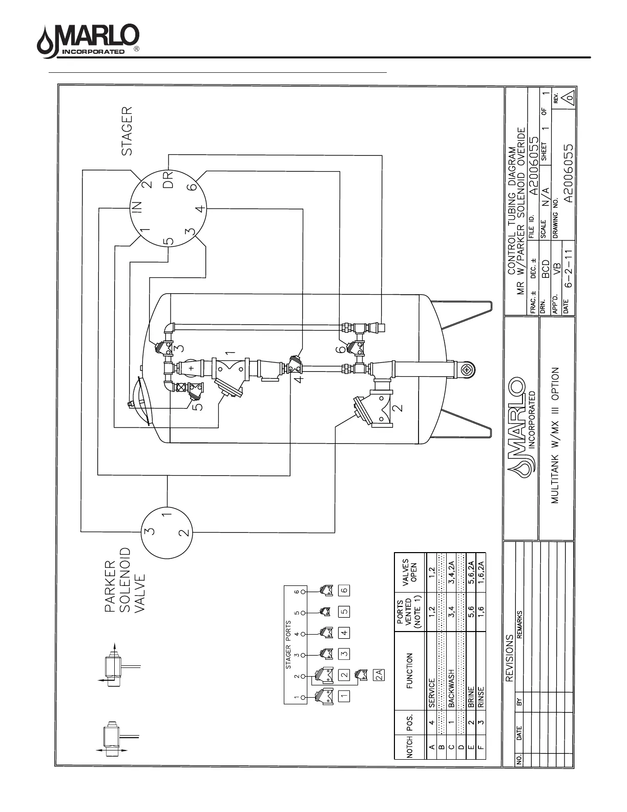
TUBING DIAGRAM - VALVE NEST - MULTITANK - PARKER SOLENOID
Note: All valves normally open except optional valve 2A.
1
3
2
Flow
Solenoid Energized
1
3
2
Flow
Solenoid De-energized
Energized To Close
TheNXTStagercontrolcanoperateanoptional24VAC
solenoidtocontrolwhenatankisoffline.Thissolenoidis
electricallyconnectedtothe"lowerdrive"connectiononthe
circuitboard,andcontrolpressureisrunthroughthesolenoid
totheserviceoutletdiaphragmvalve.
Thesolenoidinstalledatthefactoryisauniversaltype.Itis
plumbedinanenergizetocloseconguration.
WhenatankentersRegenerationorStandbythesolenoidis
energized.Pressurefromsolenoidport1passestoport2.The
diaphragmvalve#2willclose.
WhenatankentersInServicethesolenoidisde-energized.
Theinletpressuretosolenoidport2isstopped.The
diaphragmvalveisventedthroughsolenoidport2toport3
(drain).Thevalve#2opens.