MR 150M–1050M SINGLE – MXIII CONTROLLER
OPERATION
16
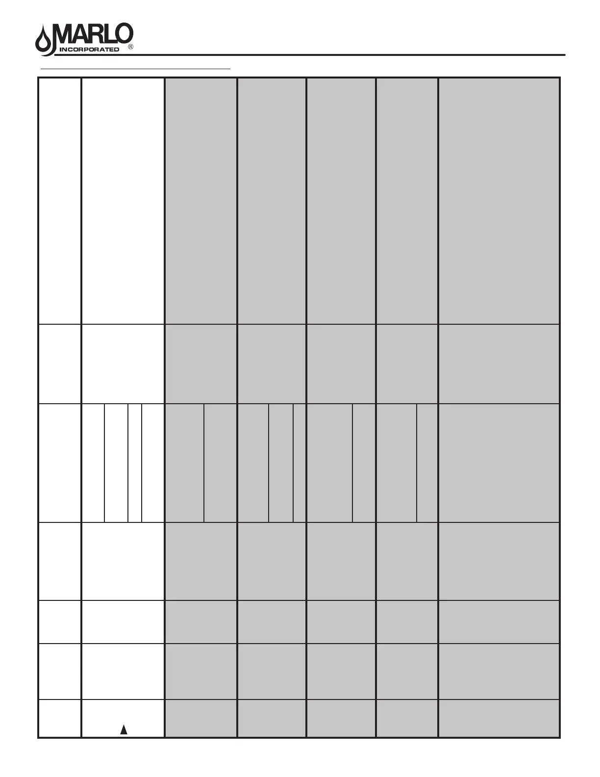
FEATURES OF THE MX III CONTROLLER
System
Number
System
Description
# of
Tanks
Connect meter
and/or remote
regeneration input
to...
Regeneration Type
Service Outlet
Valve controlled
by...
Operation Discussion
4 Single Unit 1 #1 Controller
Time Clock:
No Meter
Stager
(no solenoid
required)
Single tank conguration. During Regeneration no water avail-
able to service unless optional bypass valve #2A installed.
Immediate:
One Meter
Delayed: One Meter
Remote Signal Start: No
Meter
5 Interlocked 2, 3, or 4 Each Controller
Immediate: All Meters
Stager
(no solenoid
required)
All tanks in parallel supplying treated water. Each unit in the system
will have its own ow meter/sensor input. The control will delay
the start of Regeneration if another unit is already in Regenera-
tion. Once that unit has completed a Regeneration cycle, and has
returned to Service,the unit with longest regeneration queue time will
begin Regeneration. No more than one unit will be in Regeneration
at a time.
Remote Signal Start: No Meter
6
Series
Regeneration
2, 3, or 4 #1 Controller Only
Immediate: One Meter
Stager
(no solenoid
required)
All tanks in parallel supplying treated water. Only #1 control will
monitor ow meter/sensor input. When a regeneration is required
for the system, it will regenerate valve address #1 rst, immediately
followed by #2, then #3, then #4 if installed. No more than one unit
will be in Regeneration at a time.
Delayed: One Meter
Remote Signal Start: No Meter
7
Twin
Alternating
2 #1 Controller Only
Immediate: One Meter
Solenoid
One tank online supplying treated water, one tank in Standby. Only
#1 control will monitor its ow meter/sensor input. Regeneration of
a unit will begin after the other control has left Standby and returned
to Service. When the Regeneration cycle is complete, the regener-
ated unit will enter Standby. Standby on each tank is controlled by a
solenoid connected to the service outlet valve of that tank.
Remote Signal Start: No Meter
9
Multiple Tank
Alternating
2, 3, or 4 Each Controller
Immediate: All Meters
Solenoid
One, two, or three tanks online supplying treated water, one tank in
Standby. Meter/sensor input is required on each tank. Regeneration
of a unit will begin after the other control has left Standby and re-
turned to Service. When the Regeneration cycle is complete, the re-
generated unit will enter Standby. Standby on each tank is controlled
by a solenoid connected to the service outlet valve of that tank.
Remote Signal Start: No Meter
14
Demand
Recall
2, 3, or 4 Each Controller Immediate: All Meters Solenoid
Meter/sensor input is required on each tank. Unit #1 will begin
In Service with #2, #3, and #4 (if installed) will begin in Standby.
At least one unit is In Service at all times. When ow rate to the
Primary Service Unit increases to a user specied rate, the next
unit in sequence will move from Standby to Service. As the ow rate
falls below the user specied rate subsequent tanks will return to
Standby. When the Primary Service Unit regenerates, the next unit
in sequence will become the new Primary Service Unit. As each
units capacity is reached the controller will initiate a Regeneration
of that unit. Depending on the number of units in the system, and
ow rate demand the regenerated unit will then be placed either into
Standby or Service. Only one unit will be in Regeneration at a time.