MR 150M–1050M SINGLE – MXIII CONTROLLER
INSTALLATION
10
INSTALLATION INSTRUCTIONS
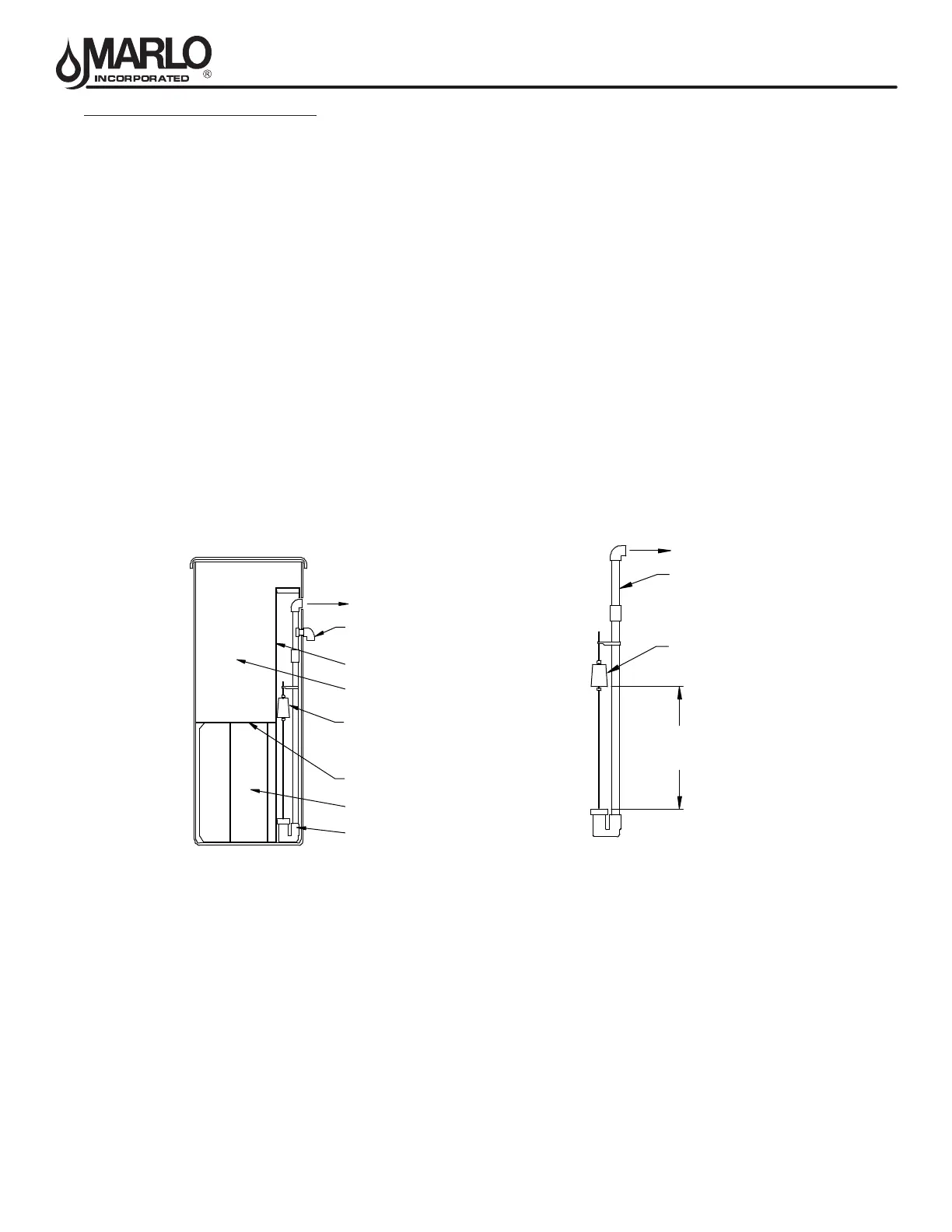
BRINE TANK INSTALLATION
1. The brine tank should be installed on a smooth level surface. If none is available, the tank should be placed on a
smooth piece of exterior plywood and leveled by placing shims underneath the plywood.
2. Make sure that the salt shelf inside the tank is level and that the brine well is near to vertical as possible. Check
the specications table and make sure that the oat setting is the proper height for the model provided. Brine
tanks are shipped with the oat set for maximum salting. If incorrect, slide the oat to the proper setting. Float
should be approximately one inch above grid plate.
3. Place brine valve into the brine well and set at the bottom of the brine tank. Note: If minimum brine draw is de-
sired, remove the pipe nipple and coupling from the brine assembly. Install remaining brine valve assembly into
elbow using Teon tape or Teon paste, and set oat to minimum salt level see Specication Table for settings.
Place brine valve into brine well. Brine valve assembly will not sit on bottom of brine tank.
4. Connect the brine valve to the brine injector. Open the manual injector feed water valve and allow the brine tank
to ll with water. To speed this process the tank can be lled with a garden hose to about 2” below the platform.
The tank will continue to ll until the oat rises and shuts of the ow (approximately 1” above the platform).
Note: In the process of making brine for the rst regeneration, the solution volume will increase (one gallon of wa-
ter will be 1.2 gallons of brine). The nal level of the liquid will be several inches above the platform.
5. If the rell water shuts o below the platform or too far above the platform, the brine valve should be removed and
the oat adjusted up or down until is shuts o approximately 1” above the platform. Place the brine well cap seal
in place and open the manual valve in the brine line to the softener tank.
TO INJECTOR
OVERFLOW
(PIPE TO DRAIN)
FLOAT
BRINE VALVE
LIQUID BRINE
DRY SALT
STORAGE
SALT SHELF
BRINE WELL
TO INJECTOR
TOP
EXTENSION
BRINE VALVE
FLOAT HEIGHT
FLOAT