MR 150M–1050M SINGLE – MXIII CONTROLLER
OPERATION
20
CONTROLLER DISPLAY FEATURES
VALVE STATE:
INI (Initializing)
INI will display on the screen for 30 to 45 seconds when initializing after a power failure reset or programming.
RGQ (Regeneration Queued)
RGQ indicates that the reserve has been entered in a delayed system and regeneration has been queued.
When in the main screen, press the Extra Cycle button to toggle service (SRV) with RGQ.
Service (SRV)
SRV will display when the unit is in service.
LCK (Lock)
Lock will be displayed when the terminal/remote input block P4 on the circuit board is switched to “lock”.
See the “Network/Communication Cables & Connections” section of this manual.
LED STATUS LIGHTS:
Blue LED:
Illuminates while the unit is in service and no errors exist. The unit will always be in service unless a
regeneration trigger has occurred (green LED light will be displayed).
A blinking blue light indicates the timer is in service, and queued for regeneration.
Green LED:
Illuminates when the unit is in Regeneration mode, unless an error condition exists.
A blinking green light indicates the timer is in standby, and not in regeneration.
Red LED:
Illuminates when there is an error.
FLOW INDICATOR:
A rotating line (appearing as a rotating star shape) will display on the screen when ow is going through the
the meter.
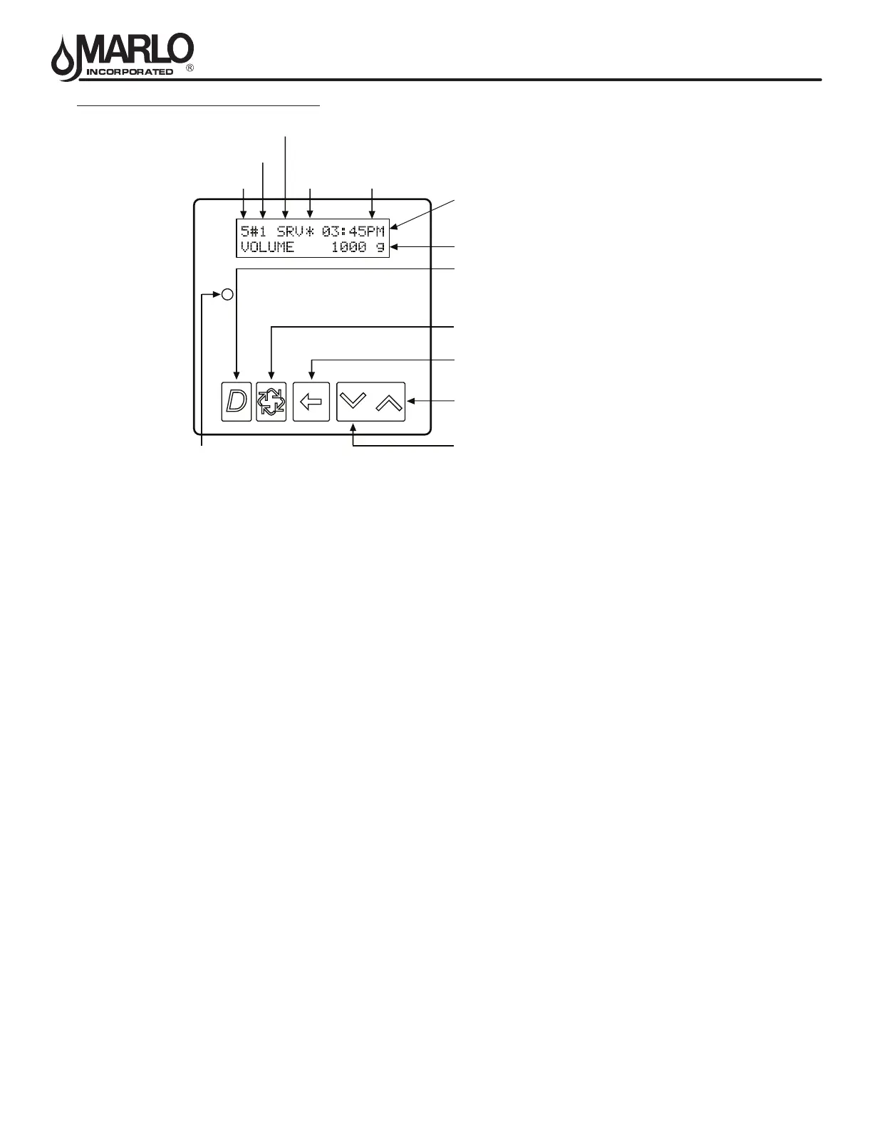
System
Number
Valve
Address
Valve State
(SBY, SRV, INI, CHG, LCK)
Flow
Indicator
Time
of Day Display Screen
Time of Day alternates with Error Screen
Example: Valve #, Volume Remaining,
Errors
Diagnostic Button
View Flow Rate, Peak Flow Rate, Totalizer, Hours
Between Last Two Regenerations, Hours Since Last
Regeneration, Adjustable Volume Remaining, Valve
Position, Send & Receive Errors, Software Version
Extra Cycle Button
Cycle Valve in Regeneration/Cycle Programming Steps
Shift Button
Adjusts Values to the Left
Up Button
Adjusts Values Up
Down Button
Adjusts Values Down
Volume Remaining
Status LED