53D0419 17
VENT INSTALLATION
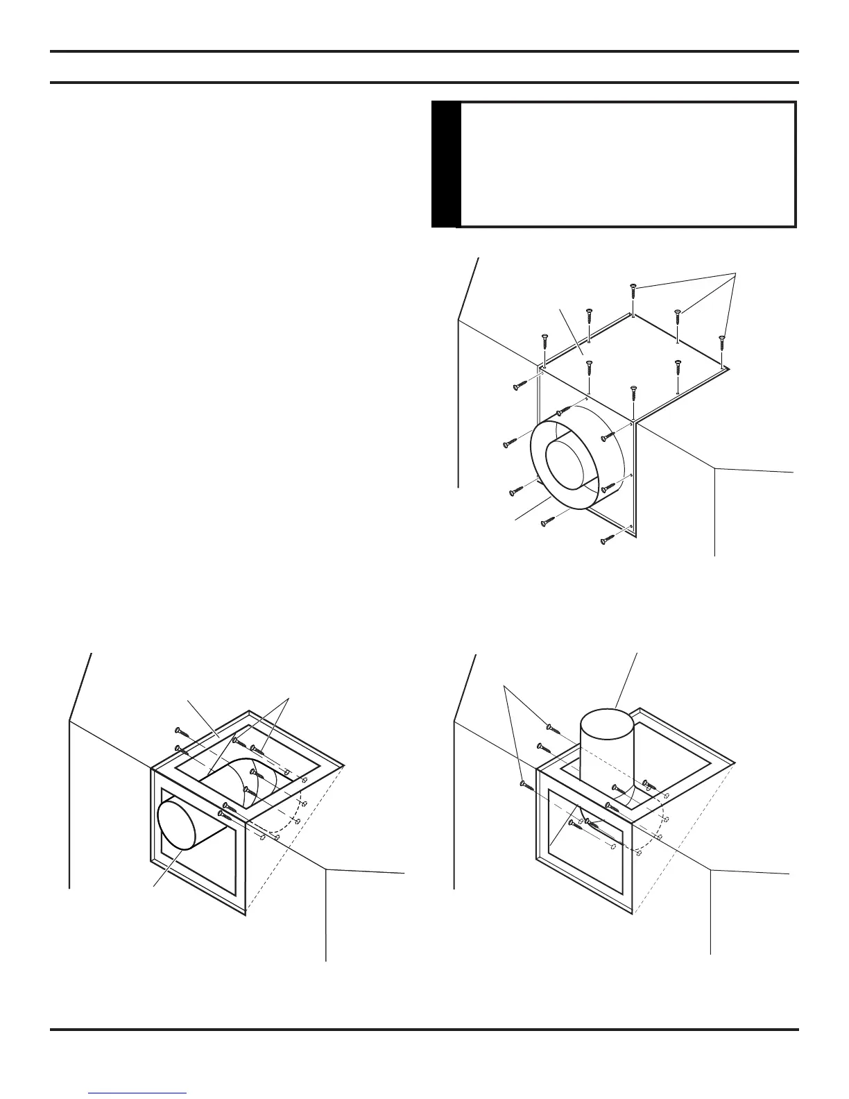
OPTIONAL TOP VENT APPLICATION
The appliance is shipped as a rear vent unit. If the installation
layout requires the unit to be a top vent conguration the appli-
ance can be converted by following the steps below.
When removing and retting the plates and adapter be sure the
associated gaskets are undamaged and retted as required.
1. Remove the eight (8) screws securing the ue pipe adapter
to the replace body. See Figure 13.
2. Set the ue pipe adapter aside, complete with the gasket.
Do not damage the gaskets as the adapter and gasket must
be retted.
3. Remove the eight (8) screws securing the ue pipe cover to
the top of the intake box and remove the cover and gasket.
See Figure 13.
4. Remove eight (8) screws securing the ue pipe to the back
of the intake box and remove the pipe and gasket. See
Figure 14.
5. Replace ue pipe to top of rebox. Ensure the gasket is in
place and undamaged. Secure with eight (8) screws. See
Figure 15.
6. Place the ue pipe cover and gasket removed in step 3 over
the ue opening in bottom of the intake box.
7. Ret the ue pipe adapter and gasket to the top of re-
place. Secure the adapter with eight (8) screws removed
in step 1.
After conversion to top vent
configuration the 4" (100mm) flue pipe
should be concentric within the 6
5
/8"
(175mm) outer collar (within
1
/4").
WARNING
Figure 13 - Removing sixteen (16) Screws from
Flue Pipe Adapter and Flue Pipe Cover
Figure 14 - Removing Flue Pipe
Figure 15 - Attaching Flue Pipe to Top
Vent Configurations
Screws
Flue Pipe
Cover
Flue Pipe
Adapter
Flue
Cover
Flue Pipe
Screws
Flue Pipe
Screws
 Loading...