– User and Installation Manual
Step 8. Integrate a fuse holder in the positive battery wire
but do not place the fuse yet!
Fit crimp-on ring terminals to the DC cables.
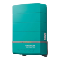
Connect the DC cabling of the battery bank;
positive to +, negative to – .
Models 3500W, 4500W, 5000W offer two ways to
connect DC cabling: one thick cable or two
smaller diameter cables.
Models1500W, 2000W, 3000W:
Models 3500W, 4500W, 5000W:
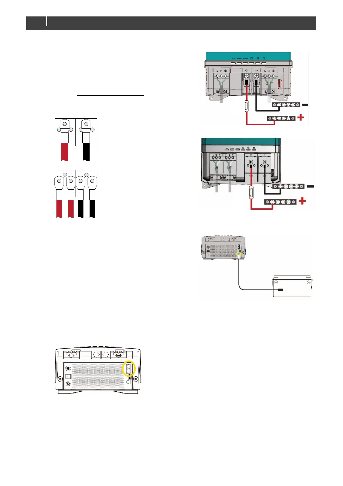
Step 9. Attach the battery temperature sensor to the
casing of the battery bank. Then plug the
temperature sensor cable into the “temp.sensor"
jack.
Note: Lithium-ion batteries require no
temperature sensor.
Step 10. On the left side of the CombiMaster Inverter/Charger check the grounding system jumper or
busbar. Out of the box the setting meets US requirements for a standalone unit. See section
4.5.3 on page 17 for details.
Step 11. Option: Connect the CombiMaster Inverter/Charger to the CZone or MasterBus network. See
section 4.5.4 for more information on network wiring.
Use the center bolts to connect
single DC cables.
Use the outer bolts to connect
double, side by side, DC cables.