HOW IT WORKS
3.4 REMOTE CONTROL PANELS
There are three remote panels available for the Mass
Combi. The Inverter Charger Control (ICC) panel and the
AC Power Control (APC) panel are specially designed for
the Mass Combi. The Mass Inverter Charger Control
(MICC) is a universal panel. However, it is not possible to
connect all three panels at the same time: you can either
use the combination of ICC and APC or the Masterlink
MICC panel only.
The remote panels are connected to the Mass Combi via a
modular communication cable with two RJ 12 connectors.
The maximum length of communication cable should not
exceed 15m/49ft. The cables are available in the following
length:
Art. Nr. Description
6502001030 Modular communication cable, 6m/19ft
6502100100 Modular communication cable, 10m/33ft
6502100150 Modular communication cable, 15m/49ft
3.4.1 Remote panel ICC
Figure 10: Remote panel ICC
The optional ICC panel provides the same functions as the
user panel on the Mass Combi. However, with this remote
panel you have the convenience to operate the Mass
Combi remotely.
3.4.2 Remote panel APC
Figure 11: Remote panel APC
The APC panel has extended functions such as setting
remotely the Power sharing value and monitoring your
“AC-load”. This APC remote panel is optional (see chapter
10 for ordering information).
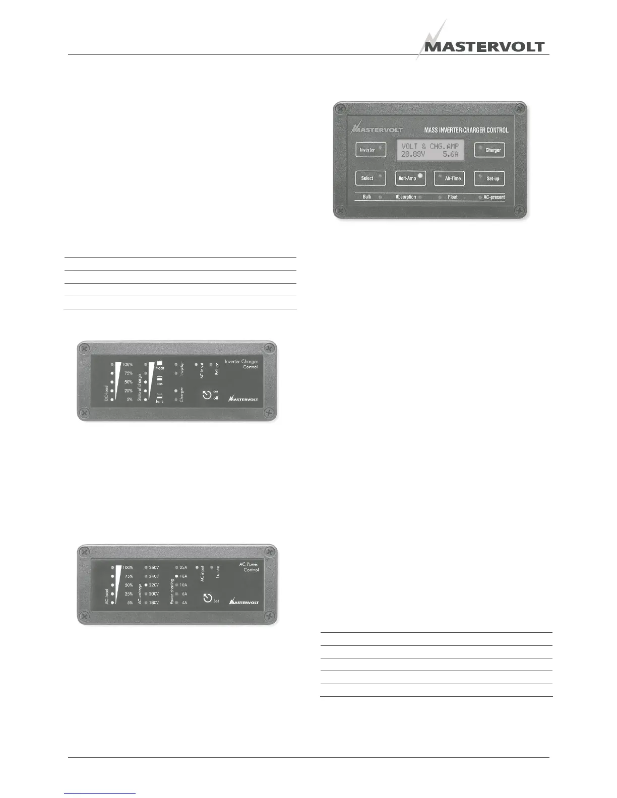
3.4.3 Masterlink MICC panel
Figure 12: Masterlink MICC panel
The Masterlink MICC panel (art. no 70403105) is a digital
remote panel that has additional features compared to the
ICC and APC panel. This sophisticated panel is not only a
remote control panel to switch on and off your Mass
Combi but also a battery consumption meter for read-out
of the exact state-of-charge of your battery by means of a
shunt. (included with the delivery of the Masterlink MICC)
When the battery is reaching a low voltage set point or a
low state-of-charge an alarm can be raised. This can be
used to start up the generator.
The information provided includes reading voltage,
current, consumed Ah, time remaining and remaining
capacity as a percentage of the maximum available
battery capacity. A well-lit LCD screen also displays direct
online data or historical information. A protective back box,
easy to install, is included as standard for protecting the
electronic components. This panel is suitable for
MasterVision, Mastervolt’s modular switchboard system.
3.5 ALARM CONTACTS
The Mass Combi is equipped with an integrated alarm
function. External equipment can be controlled by the
potential free contacts of this alarm (see 5.8.2). The
maximum switch current of the relay is 1A. By default the
relay will be activated when the DC-voltage is out of range,
after a delay of 30 seconds. See table below. Other
functions can be programmed by means of MasterAdjust
software (see section 3.6)
Nominal voltage: 12V 24V
Under voltage ON: 10.0V 20.0V
Under voltage OFF: 11.0V 22.0V
Over voltage ON: 16.0V 32.0V
Over voltage OFF: 15.5V 31.0V
Table 3
14 EN / Mass Combi 12/1200-60 & 24/1200-35 / EN

 Loading...


