INSTALLATION
EN / Mass Combi 12/1200-60 & 24/1200-35 / June 2007 25
5.8.1 Wiring instructions for the Mass Combi
See figure 20.
1 See reference M. Connect the external AC-source to
the AC-input of the Mass Combi. Integrate a fuse
(value depending on the used wire diameter with a
maximum of 50Amps) and a Residual Current Device
(RCD) into this wiring.
2 See reference d. Connect the AC-output POWER of
the Mass Combi to the power distribution group.
3 See reference e. Connect the output SHORT BREAK
of the Mass Combi to the SHORT BREAK distribution
group. Integrate a Residual Current Device (RCD) into
this wiring.
4 See reference f. Run the DC-cables between the
DC-distribution and the Mass Combi. Connect the red
cable to the plus (+) connection, the black cable to the
minus (–) connection. Do not install the DC-fuse of the
DC-distribution before the entire installation is
completed (see chapter
7).
5 See reference g. Attach the temperature sensor to
the battery and run the cable into the Mass Combi
and connect the RJ12 connecter to the
“TEMP.SENS”-connector (Data Bus Connections)
6 Option: if you want to make use of the possibility to
give a maintenance charge to a small battery set (like
a starter battery), run a 6mm² /AWG10 red cable with
a fuse holder between the positive pole of the starter
battery and Mass Combi. See figure 20, reference h.
Fix the cable with an insulated faston to the “+5A”-
connection. Integrate a 25 Amps–T fuse in this wire.
The negative pole of this battery must be connected
to the negative pole of the service battery.
7 See reference i. If you want to install an ICC remote
control panel (optional), run the communication cable
between the Mass Combi and the panel. Connect the
RJ12 connector to the “REMOTE”-input (Data Bus
Connections)
8 Other panels than the ICC remote control panel must
be connected to the “QRS232”-connection; reference
j. Refer to the applicable installation manual for
instructions.
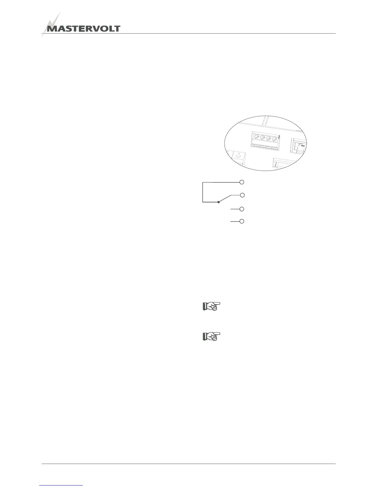
5.8.2 Alarm contacts
Connectors 1 to 4 are internally linked as follows:
The alarm contact is switched to “Normally Open” in case
of an alarm situation, see section
3.5.
5.9 SETTINGS
See chapter 6 for DIP switch settings
NOTE:
Adjust the DIP switches prior to
commissioning!
NOTE
When using a Masterlink MICC remote panel:
x See section 6.2.5 for DIP switch setting at the
Mass Combi;
x See section 4.4 of the user’s manual of the
Masterlink MICC to enable the Mass Combi
setting.
Figure 21 alarm contacts
1
-
2
-
3
-
4
1 (C) Common
2 (NC) Normally Closed
3 (NO) Normally Open
4 Not used

 Loading...


