32 CONTENTS
2 Strobe-Out2 (+) -> Collector White
3 Strobe-Out2 (-) -> Emitter Brown
4 Trigger-In2 (+) -> Anode Green
5 Trigger-In2 (-) -> Cathode Yellow
6 Sync-In2 (+) -> Anode Gray
7 Sync-In2 (-) -> Cathode Pink
8 GND (camera power) Blue
Recommended plugs for 8-pin Binder series 711:
• 711: Binder ordering no. 99-0479-100-08 / 99-0479-102-08
Detailed information: http://www.binder-connector.de
8.1.2.6 Pinning J5 (Power supply (floppy))
You can connect a free power supply cable for floppy drives on connector J5 to increase the available current on the
power supply pins on J3 and J4 to 2A.
Pin Signal
1 +12 V
2 Ground
3 Ground
4 Not connected
8.1.2.7 Pinning J6 (internal digital I/Os)
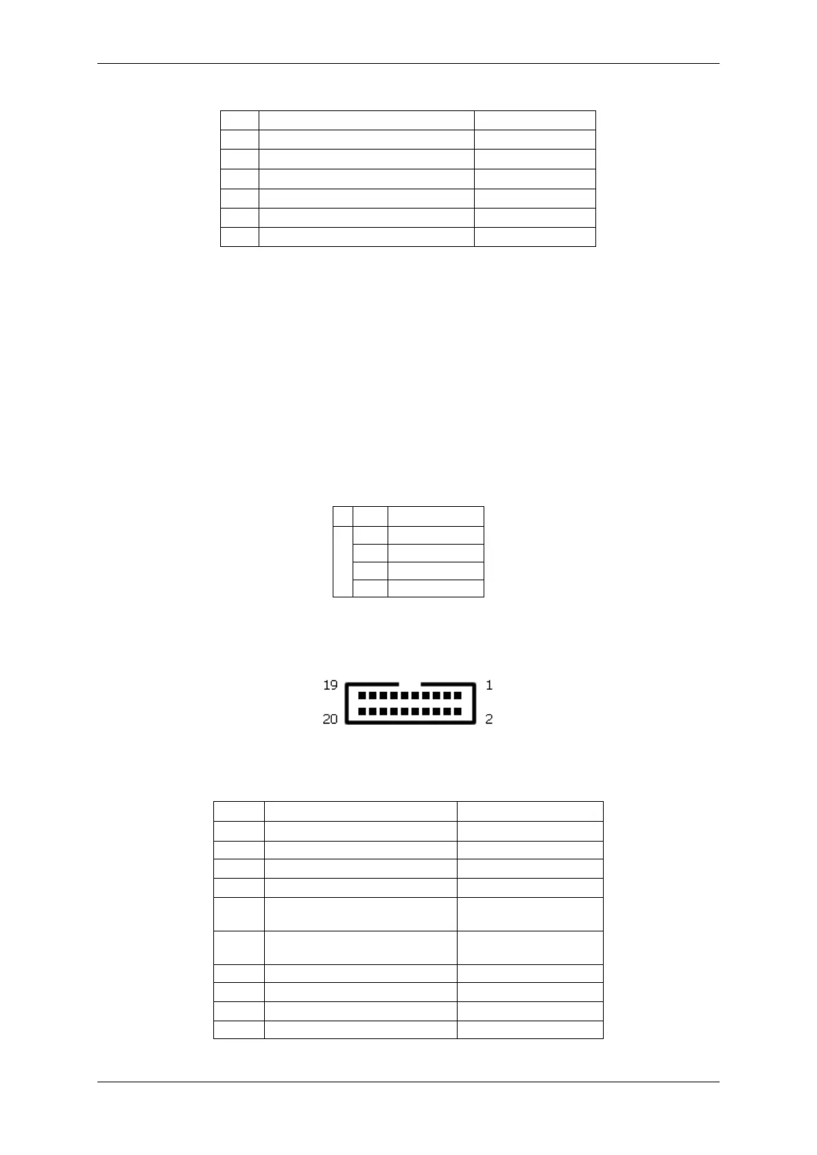
Figure 9: J6
Pin Signal Signal direction
1..5 used internally (do not connect!)
6 Ground Ground
7 +5V out +5V DC power supply
8 +3.3V out +3.3V DC power supply
9..12 GPIN0..3 LVTTL(3.3V) input.
not 5V tolerant!
13..16 GPOUT0..3 LVTTL(3.3V) output.
not 5V tolerant!
17 Ground Ground
18 +12V DC Out +12V DC power supply
19 +12V DC Out +12V DC power supply
20 Ground Ground
MATRIX VISION GmbH