Man19755 Rev. B
The Matrix Impact and Impact
2
Equalizer allows the Tip to Tip spacing of the pipettor to change. This allows pipeting into
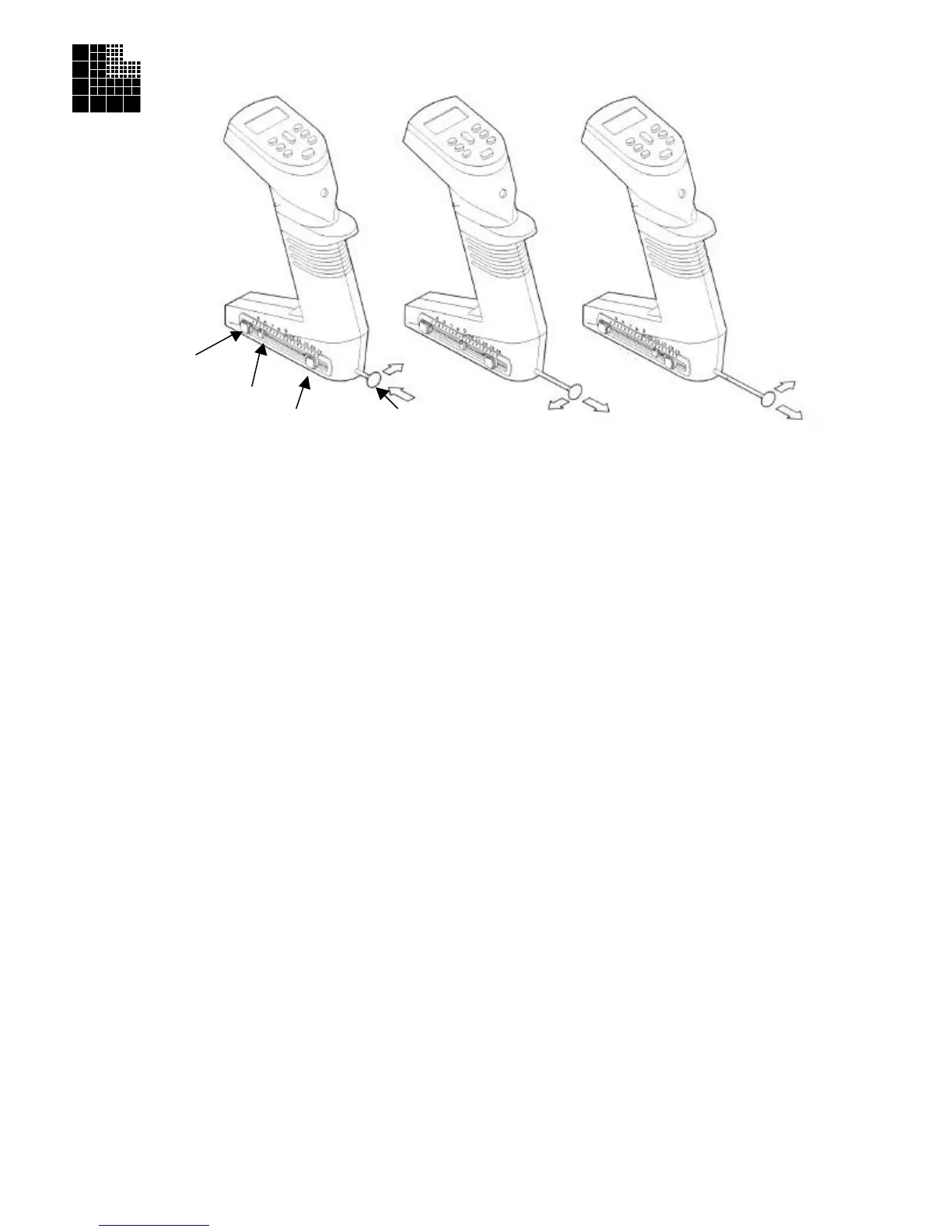
or between vessels of varying center to center configurations. The set button(s), indicator and control rod all work together
to change the distance between the tips (see figure A).
To attach tips, the control rod should be in position such that the indicator is set at 9 mm (figure B). In the case of the
Equalizer384 (the Equalizer with two set buttons), tips arranged in racks of 384 can be attached when the indicator is set at
the 4.5 mm mark. Once tips are attached, follow the steps below to change the pipettor to a new tip spacing.
Matrix Equalizer:
1. Depress the set button using your thumb or finger.
2. While depressing, slide the set button to the desired tip-to-tip spacing marker on the window. Release the set button to
lock the spacing.
3. Using the control rod, slide the tips into the desired position. The indicator in the window will also move and will nest
into the set button when the desired position is achieved.
Matrix Equalizer384:
1. To set the tip spacing for the vessel with the widest spacing, depress the outer set button (the button closest to the
control rod) using your finger or thumb.
2. While depressing, slide the set button to the desired tip-to-tip spacing marker on the window. Release the set button to
lock the spacing.
3. Check the spacing by using the control rod to slide the tips into position. The indicator in the window will also move
and will nest into the set button when the desired position is achieved.
4. For the vessel with the tightest spacing (from 4.5mm - the spacing for 384 well plates), depress the other set button
using your thumb or finger and repeat steps 2 and 3.
5. In the case of 8 channel Equalizer384 pipettors, when pushing or pulling the control rod past the 9 mm position, if
pressure is applied to the back side of the control rod (see figure B), a detent will be noticeable. This will indicate the
96 well or tip mounting position. Conversely, by applying pressure to the front side of the control rod (see figure C),
the detent can be by-passed for smoother slide operation.
Note: For maximum accuracy when adjusting the spacing of the tips from a compressed position to an expanded position it
is recommended that the control rod be actuated beyond the desired spacing and then compressed to the desired dimension.
This will maximize the spatial accuracy between the individual tips.
Important: Do not attempt to slide the set button(s) without depressing. Moving the set button(s) without first disengaging
will cause premature wear on the mechanism.
Important: Do not attempt to disassemble the unit. Please contact our Technical Services Department at 800-345-0206 for
all service related issues.
(Equalizer 384 only)
Indicator
Set Button
Control Rod
Figure A Figure B Figure C