78 Appendix B: Technical reference
Serial port connectors
The 2 serial port connectors are 9-pin, D-subminiature male connectors (DB-9
1
).
Although they are both configured for the RS-232 standard, the configuration of
the top connector can be changed to accommodate the RS-485 standard by
adjusting the unit’s settings in the UEFI Setup utility. For information, refer to
Appendix C: Matrox 4Sight EV6 UEFI reference.
The top serial port connector (labeled Com1/RS-232/485) in RS-485 mode is
not terminated by default. If your configuration requires that you instantiate
termination of the RS-485 connection, refer to the RS-485 termination connector
subsection of the Pinout descriptions of internal connectors section, later in this
appendix.
IN8+, IN8- AUX_ISOIND_IN8 M_AUX_IO15
Isolated, industrial auxiliary signal 15 (input).
1
OUT1+, OUT1- AUX_ISOIND_OUT1 M_AUX_IO0
Isolated, industrial auxiliary signal 0 (output).
2
OUT2+, OUT2- AUX_ISOIND_OUT2 M_AUX_IO1
Isolated, industrial auxiliary signal 1 (output).
2
OUT3+, OUT3- AUX_ISOIND_OUT3 M_AUX_IO2
Isolated, industrial auxiliary signal 2 (output).
2
OUT4+, OUT4- AUX_ISOIND_OUT4 M_AUX_IO3
Isolated, industrial auxiliary signal 3 (output).
2
OUT5+, OUT5- AUX_ISOIND_OUT5 M_AUX_IO4
Isolated, industrial auxiliary signal 4 (output).
2
OUT6+, OUT6- AUX_ISOIND_OUT6 M_AUX_IO5
Isolated, industrial auxiliary signal 5 (output).
2
OUT7+, OUT7- AUX_ISOIND_OUT7 M_AUX_IO6
Isolated, industrial auxiliary signal 6 (output).
2
OUT8+, OUT8- AUX_ISOIND_OUT8 M_AUX_IO7
Isolated, industrial auxiliary signal 7 (output).
2
1. Supported inputs: interrupt/poll (M_IO_STATUS), timer clock (M_TIMER_CLOCK_SOURCE), timer arm
(M_TIMER_ARM_SOURCE), I/O command list counter source, reference latch trigger
(M_REFERENCE_LATCH_TRIGGER_SOURCE), quadrature input bit 0 or 1
(M_ROTARY_ENCODER_BITn_SOURCE), rotary decoder counter reset source
(M_ROTARY_ENCODER_RESET_SOURCE)
2. Supported outputs: user bit (M_USER_BITn), timer output (M_TIMERn), or an I/O command register bit
(M_IO_COMMAND_LISTn+M_IO_COMMAND_BITn).
1. More accurately known as DE-9.
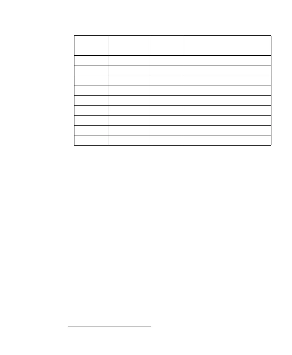
Wire-terminal Hardware signal
name
MIL constant
for auxiliary
signal
Description