Pinout descriptions of external connectors 79
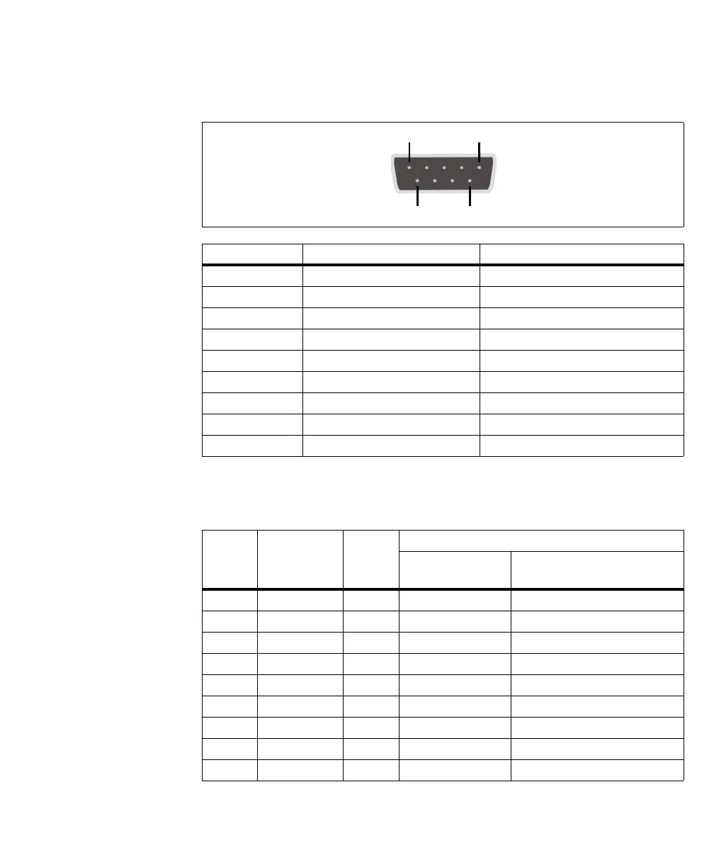
The pins in the bottom DB-9 connector have the following pinout:
The pins in the top serial port connector (RS-232/RS-485 standard) have the
following pinout:
Pin Signal Description
1CD Carrier detect.
2RXD Receive data.
3TXD Transmit data.
4 DTR Data terminal ready.
5 GND Ground.
6 DSR Data set ready.
7 RTS Request to send.
8CTS Clear to send.
9 RI Ring indicator.
Pin Hardware
signal name
I/O Description
RS-232 standard RS-485 standard with resistor
termination not activated
1
1. To set the RS-485 termination, see RS-485 termination connector subsection of the Pinout descriptions of internal connec-
tors section, later in this appendix.
1 NC I Not connected. Not connected.
2 RXD I Receive data. RXD -.
3 TXD O Transmit data. TX -.
4 NC O Not connected. Not connected.
5GND - Ground. Ground.
6 NC I Not connected. Not connected.
7 RTS O Request to send. TX +.
8 CTS I Clear to send. RXD +.
9 NC I Not connected. Not connected.