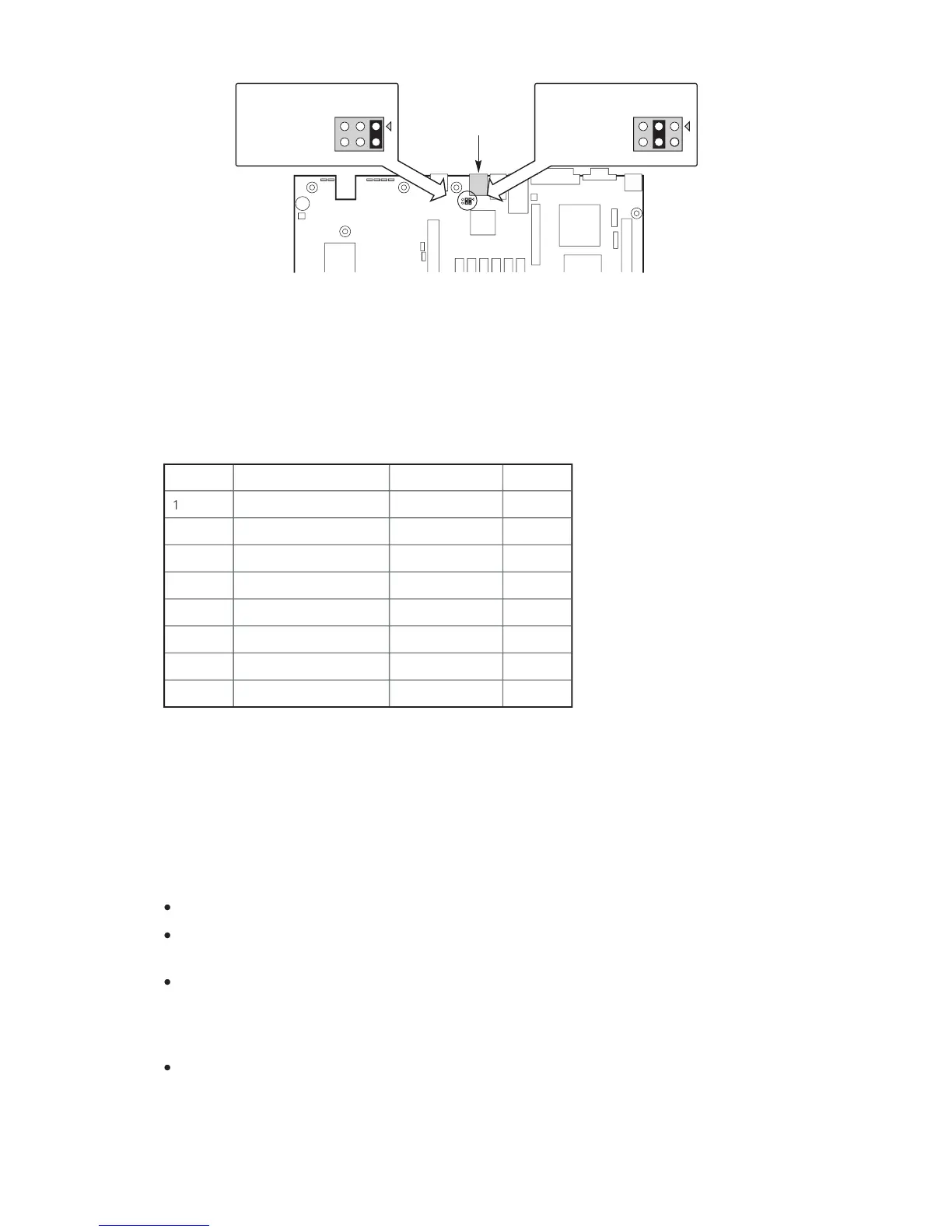
For server applications that require a DB9 serial connector, you must use an 8-pin RJ-45-
to-DB9 adapter. The following table defines the pin-out required for the adapters to provide
Table 2. Rear Serial 2 Port Adapter Pin-out
The MAXDATA PLATINUM Server Board supports the Advanced Configuration and Power
) as defined by the ACPI 2.0 specification. An ACPI aware operating system
can put the system into a state where the hard drives spin down, the system fans stop, and
all processing is halted. However, the power supply will still be on and the processors will
still be dissipating some power, so the power supply fans will still run.
The MAXDATA PLATINUM Server Board supports sleep states s0, s1, s4, and s5:
s0: Normal running state.
s1: Processor sleep state. No context will be lost in this state and the processor caches
s4: Hibernate or Save to Disk: The memory and machine state are saved to disk. Pressing
the power button or other wakeup event will restore the system state from the disk and
resume normal operation. This assumes that no hardware changes have been made to
the system while it was off.
s5: Soft off: Only the RTC section of the CSB and the BMC are running in this state. No con-
text is saved by the OS or hardware.