Comet Executive Gas Operating Principles
5-7
5.3 Exhaust System
Components that make up the exhaust system
are located in the exhaust canopy.
These components include:
• Exhaust Blower
• Sail Switch
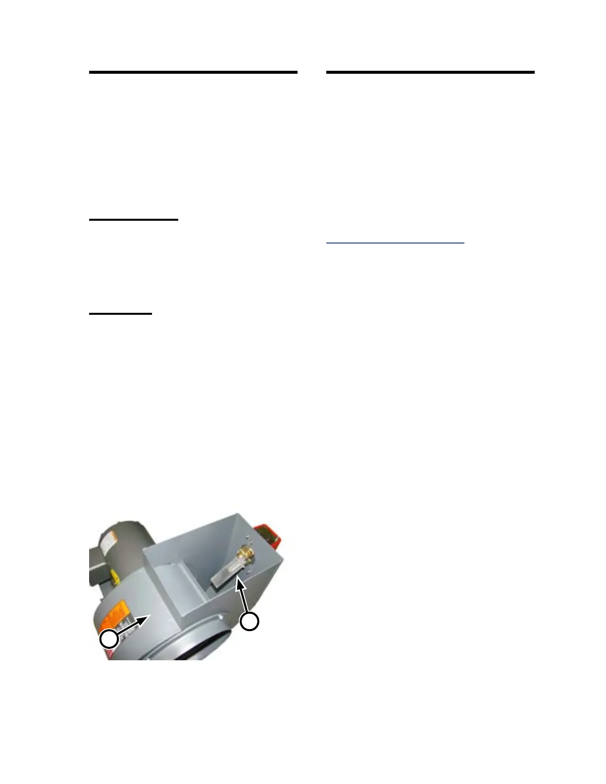
Exhaust Blower
The exhaust blower (Figure 5-6, A) draws used
air and combustion by-products from under the
canopy and discharges them through an attached
vent duct at the required rate.
Sail Switch
The sail switch (Figure 5-6, B) is located in
the discharge of the exhaust blower. The sail
switch contacts are closed when air, exhaust
combustion by-products, and excess heat are
being vented through the exhaust ductwork.
When air movement stops or is restricted in the
exhaust ductwork, the sail switch contacts open,
and the burner system shuts down.
5.4 Heating System
The heating system consists of the following
components:
• Burner System
• Temperature Control
• Temperature Sensor Contact Shoes
These systems work together to monitor and
control the operation of the heating system.
For detailed electrical information, refer to the
SCHEMATIC PARTS LIST.
Figure 5-6: The exhaust blower (A) with its sail
switch (B) should be wall mounted
within 15’ of the ironer.
A
B