30119-50 Rev. 2.2 | 23JUL2020
Page 3
INSTALLATION
2.0 INSTALLATION
After unpacking the register assembly, verify that the
meter serial number engraved on the enclosure lid is
correct. Then conrm the information on a white label
located on the bottom of the base plate (Figure 1.)
Figure 1. Meter Serial Number Placement
Enclosure lid
Baseplate
944606
2.1 Mechanical-to-FlowCom Conversion Kit Installation - Meter Mount
Note: For remote mount retrot, see section 2.2.
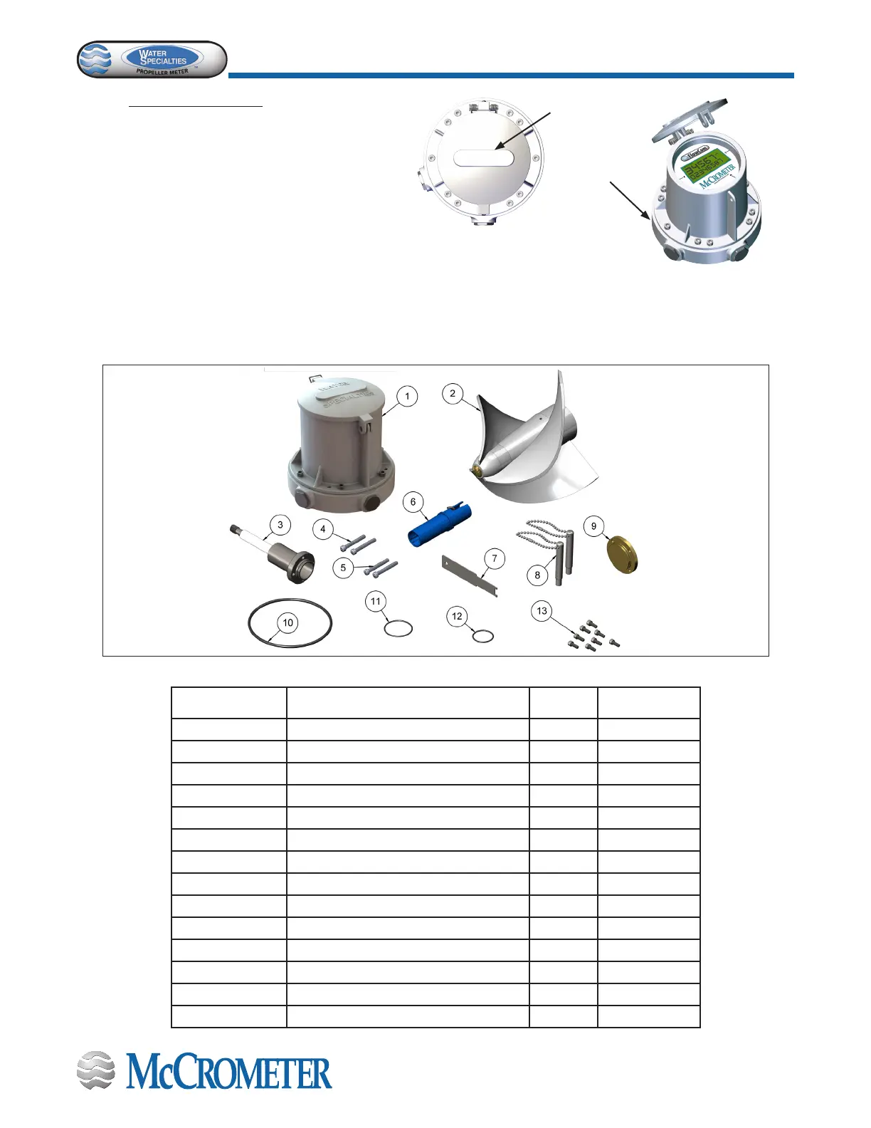
Check the parts received against the parts list and Figure 2 and Figure 3 below. Contact the factory to report any
discrepancies.
Figure 2. Conversion Kit - FC101-00-K, Meter Mount
Parts Diagram Description Quantity Part Number
1 FlowCom Unit 1 FC101-01
2 Propeller Assembly 1
Bagged parts:
3 Separator 1 4-2455-2-D
4 Screw 10-32 x 1.25” Long 2 10730
5 Screw 10-32 x 1.25” Long w/hole 2 10830
6 Sensor 1 4-2745-2
7 Reverse Thrust Brg Tool 1 T-2402X-1
8 Magnet Wand 2 FC100-M
9 Back Plate 1 2-2731-SS
10 O-Ring (243 Buna) 1 1-1551-38
11 O-Ring (028 Buna) 1 1-1551-2
12 O-Ring (022 Buna) 1 1-1551-24
13 Screw 8-32 x 7/16 SOC HD 8 1-1103-8-7

 Loading...