30119-50 Rev. 2.2 | 23JUL2020
Page 13
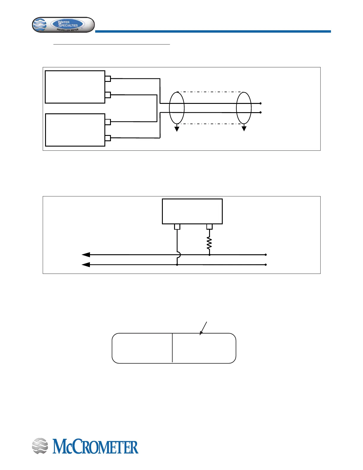
Output Wiring Connection
3.0 OUTPUT WIRING CONNECTION
3.1 Wiring Diagrams
Figure 9. Output Type: 4-20mA Current Loop (Meter-mounted version)
Housing Label:1 (Figure 11)
Instrument
(-)
(-)
(+)
(+)
Isolated
Power Supply
12-40VDC
RED
+
BLACK
-
FC100 Output Cable
GND GND
Note: This Side Is Already
Connected Internally To
Figure 10. Output Type: Optically Isolated Connection
Housing Label: 1 (Figure 11)
(+)
(-)
Power Supply
12-40 VDC
FC100 Output Cable
WHITE
+
GREEN (-)
PULSE OUT
COMMON
5K
Note: Power Supply Does Not
Have To Be Isolated From The
Ground
4-20mA
NPN OC □OPT
12-30V MAX. 50V 50 mA
RED+ BKL - WHT+ GRN -
Checked if Optically Isolated
Figure 11. Enclosure Label 1
“4-20mA / OC”
FC101 Output Cable
FC101 Output Cable

 Loading...