30119-50 Rev. 2.2 | 23JUL2020
Page 12
INSTALLATION
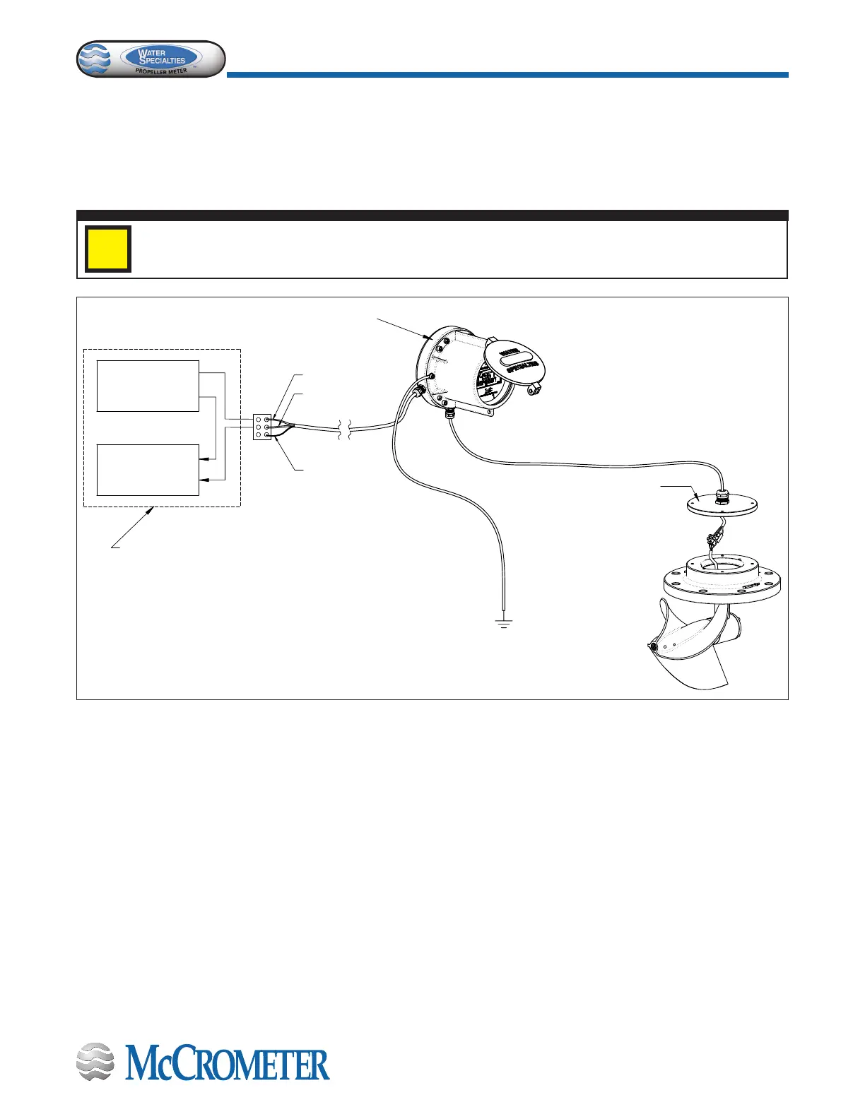
Figure 8. Grounding the FlowCom Remote Mount
NOTE: Figure 8 shows grounding requirements for FlowCom registers that are remote mount,
equipped with 4-20mA, pulse, and/or used with VFD pumps.
MOUNTING SCREWS
TO THE METER HEAD
GREEN WIRE
BOTH ENDS
CRIMPED
SENSOR CABLE
* EARTH
GROUND
4-20 CABLE
ISOLATED +24 V
DC SUPPLY
TYPICAL
SCADA UNIT
(+)
(
−
)
(+)
(
−
)
*INSTRUMENT
CABINET MUST BE
EARTH GROUNDED
RED
BLACK
SHIELD
(SILVER)
GROUND WIRE
JUMPER
NOTE: Grounding schemes
may vary depending upon
site characteristics and
installation complexity.
STEP 2: Test the FlowCom.
Test the conversion by spinning the propeller by hand and ensuring the display changes. Install the meter into the line and
mount the remote FlowCom in a convenient location.
STEP 3: Ground the Flowcom.
Following the Grounding Kit Instructions, connect the ground wire to the Flowcom and other systems that may be attached.
i
 Loading...
