12
• SL (Surround Left)
• SBR (Surround Back Right)
• SBL (Surround Back Left)
• HR1 (Height Right 1)
• HL1 (Height Left 1)
• HR2 (Height Right 2)
• HL2 (Height Left 2)
• SW1 (Subwoofer 1)
• SW2 (Subwoofer 2)
HR1 and HL1 should be forward of HR2 and HL2.
The MX100 support of Height speakers is limited to
Top Front, Top Middle and Top Rear locations.
Setting up speakers for a surround setup takes
planning, measuring and installation. Depending
on your level of expertise and available time, you
may wish to employ the services of your McIntosh
dealer for expert setup of your system. Professional
installation of in-ceiling speakers is particularly
important due to gravity and the location above your
head.
The number, types and locations of speakers are
key elements in setting up the system. There is
a multitude of possible congurations, and the
MX100 is very exible in its setup to adapt to many
of these congurations.
Often surround setups are referred to by numbers
for example 7.2.4. The rst number refers to the
number of traditional “oor” speakers (front, center
and surround). The second number is the number
of subwoofers that can be connected, and the third
number refers to the number of in-ceiling or upward
ring speakers in the setup.
The type of speaker (size and location) will be
entered later during Speaker setup. The distance of
the speaker from the listening location is manually
entered in the Speaker setup, or automatically
entered during the Audyssey
®
calibration process.
At this stage, the connection from the MX100 to the
various ampliers and powered speakers should be
made using quality balanced XLR cables.
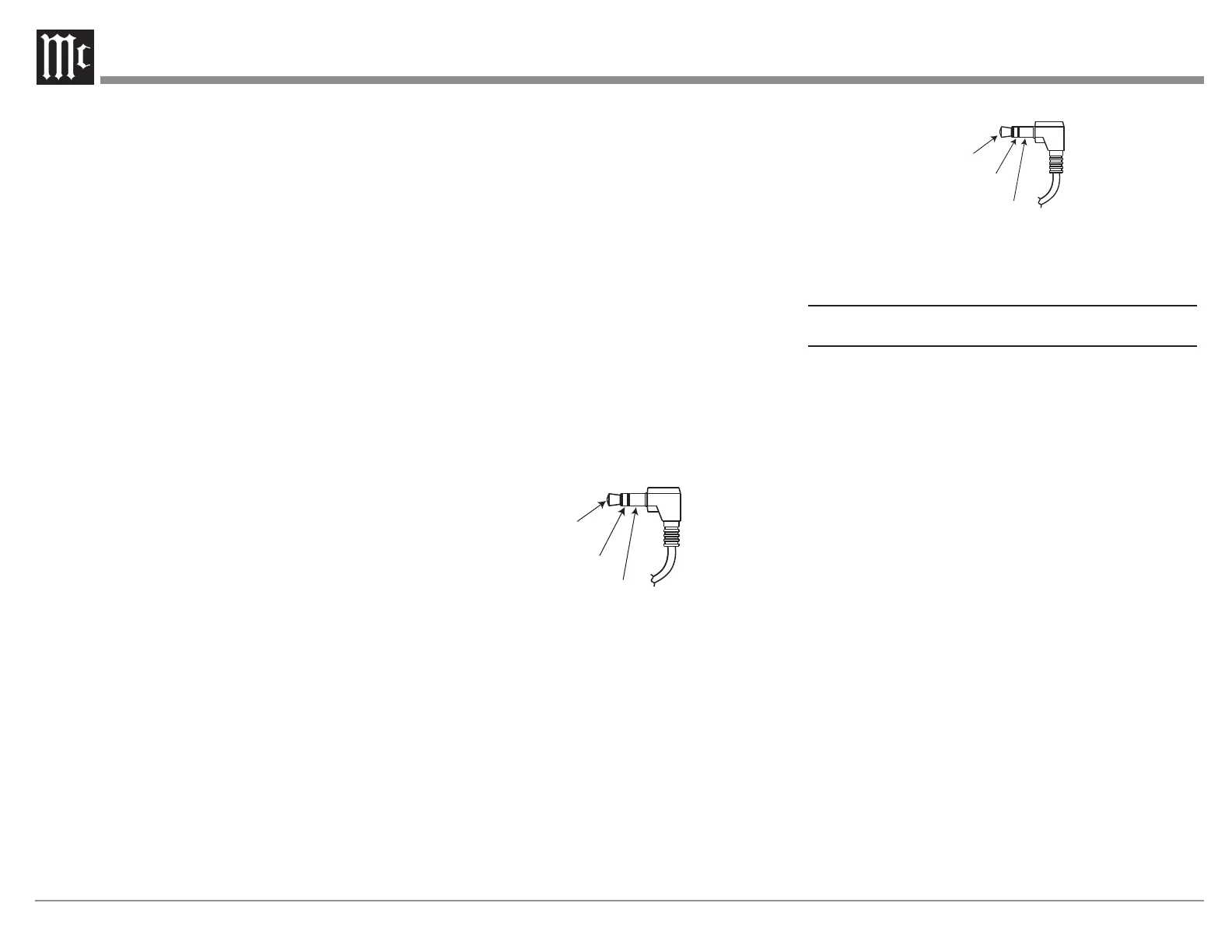
Power Control (Trigger) Outputs
The MX100 has two Power Control Outputs or
Triggers. Power Control enables power on/off
signals to go to connected components so that other
components can automatically power on (or off) as
called for by the MX100. For example, you may
want a DVD player and a certain monitor to power
on when HDMI 1 Input is selected, or you may want
all components to power off when powering off the
MX100. For Setup instructions see Trigger1 and
Trigger2 on page 21.
Connect components using a 3.5mm stereo mini
plug.
Power
Control
Meter
Illumination
Control
Ground
Data Out
The MX100 will convert IR Remote Control data
to share with McIntosh components connected to
the Data Ports. This will allow the operation of
primary functions of a source to be operated with
the MX100’s Remote Control as well as allow
units that are out of range of an IR signal to receive
commands.
Data
Signal
N/C
Data
Ground
To connect a McIntosh unit to a Data Port, use a
3.5mm stereo mini phone plug cable. See Figure 13.
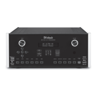
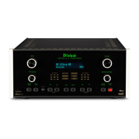
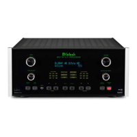
Sengs
There are two ways to change the settings of the
MX100.
• Front Panel Method using the Vacuum Flou
rescent Display (VFD) and Left Knob or
Remote Control
• Using a browser on a connected computer
Each method follows the same menu structure. Most
will nd it easier to navigate and enter information on
a computer. If you don’t have a connected computer
or the MX100 is not connected to your network, then
using the Front Panel method can accomplish almost
all the same things using some additional patience.
To use the browser method, you will need the IP
address of the MX100. This can be determined using
the Front Panel Method. After the example below
of determning the MX100’s IP Address, the browser
method will be used for examples to follow in this
manual. The submenus outlined for the browser
menus are the same for the Front Panel Menu.
Clicking the mouse button and selecting with the Left
Knob will traverse the MX100’s Setup in the same
way. To go back in the Front Panel Method, turn
the Left Knob clockwise. The last menu choice is
always “Menu Back”. Choose Menu Back to go to the
previous menu.
Figure 12– Power Control (trigger) mini plug
Figure 13– Data Out mini plug