6
What is in the box
Here is what is in the box besides all the shipping foam:
One MX100 A/V Processor
One accessory package including:
• Microphone with attached cable
• Microphone stand
• 1/2 inch male to 5/8 inch female adapter
One hardware package:
• Two Side Rack Mounting brackets
• 4 at head Philips screws 6-32x1/4”
• 4 at head Philips screws 8-32x1/4”
One manual package including this manual
One HR085 Remote Control
One AC power cord
Where to put it
The MX100 can be placed upright on a table or
shelf, standing on its four feet. It also can be custom
installed in a piece of furniture or cabinet. The four
feet may be removed for custom installations. The
four feet together with the mounting screws should
be retained for possible future use. Do not use
different size screws when re-installing the feet. With
the feet removed, the MX100 requires a ventilation
cutout. Dimensions for the panel cutout and bottom
ventilation cutout are shown in “Figure 02– Custom
cutout dimensions” on page 7.
Always provide adequate ventilation for your
MX100. Cool operation ensures the longest possible
operating life for any electronic instrument. Do not
install the MX100 directly above a heat generating
component such as a high-powered amplier. If all
the components are installed in a single cabinet, a
quiet running ventilation fan can be a denite asset in
maintaining all the system components at the coolest
possible operating temperature.
A custom cabinet installation should provide the
following minimum spacing dimensions for cool
operation:
• 2 inches (5.1cm) above the top
• 2 inches (5.1cm) below the bottom
• 1 inch (2.5cm) on each side of the MX100 so
that airow is not obstructed
• 20 inches (50.8cm) depth behind the front panel
• 1-7/16 inch (3.7cm) in front of the mounting
panel for knob clearance
Be sure to cut out a ventilation hole in the mounting
shelf according to the dimensions in the drawing. See
Figure 02 on page 7.
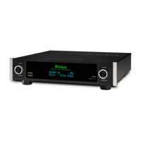
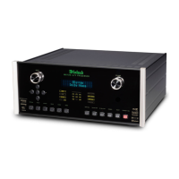
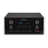
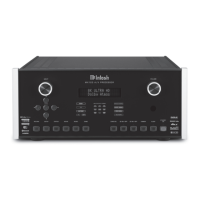
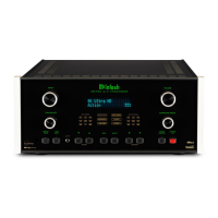
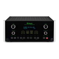
Rear View of the MX100
Side View of the MX100
Front View of the MX100
17-
1/2"
44.5cm
3-15/32"
8.8cm
4-5/16"
11.0cm
13-1/4"
33.7cm
18-1/2"
47.0cm
17-1/16"
43.3cm
.25"
.64cm
2.0"
5.0cm
34.5cm
13-19/32"
1-
5/16"
3.4cm
.5cm
3/16
"
8.2cm
3-1/4"
19"
Front View of the MX100 with Side Mount Brackets
48.3cm
16-1/2"
41.9cm
INPU T
/
M X 10 0 A V P R O C E S S O R
BD
DOLBY ATMOS
VOLU ME
PUSH - SET UP / TRIM PUSH - POW ER
INPU T
/
M X 10 0 A V P R O C E S S O R
BD
DOLBY ATMOS
VOLU ME
DSX
PUSH - SET UP / TRIM PUSH - POW ER
Rear View of the MX100
13-
1/4"
33.7cm
16-1/2"
41.9cm
HDMI
IN
1 2
3
4
RS232
TRIG 1 IR IN
TRIG 2
2
OPT
COAX
1
1
2
USB
5V/1A
SERVICE
OUT/ARC
DATA OUTSETUP MIC
SERIAL
NUMBER
75 WATTS
120V
50 60Hz
FR FL C SL SBR SBL HR1
BALANCED OUTPUTS
SR HL1 HR2 HL2 SW1 SW2
A/V P ROCESSOR
MX100
McINTOSH LABORATORY, INC.,
BINGHAMTON, NY
HANDCRAFTED IN USA WITH US AND IMPORTED PARTS
NET
DIGITAL INPUTS
Figure 01– MX100 Dimensions