Power Control Connectors
is used for connection to the trigger outputs on the
Data Out Connector
share with McIntosh components connected to the
DATA OUT port on the rear panel. This will allow
the operation of primary functions of a source to be
as allow units that are out of range of an IR signal to
receive commands.
NET Port (Ethernet / 10baseT LAN)
a network router. The network connector is located
will automatically receive an IP address from the
router. This setting can be changed.
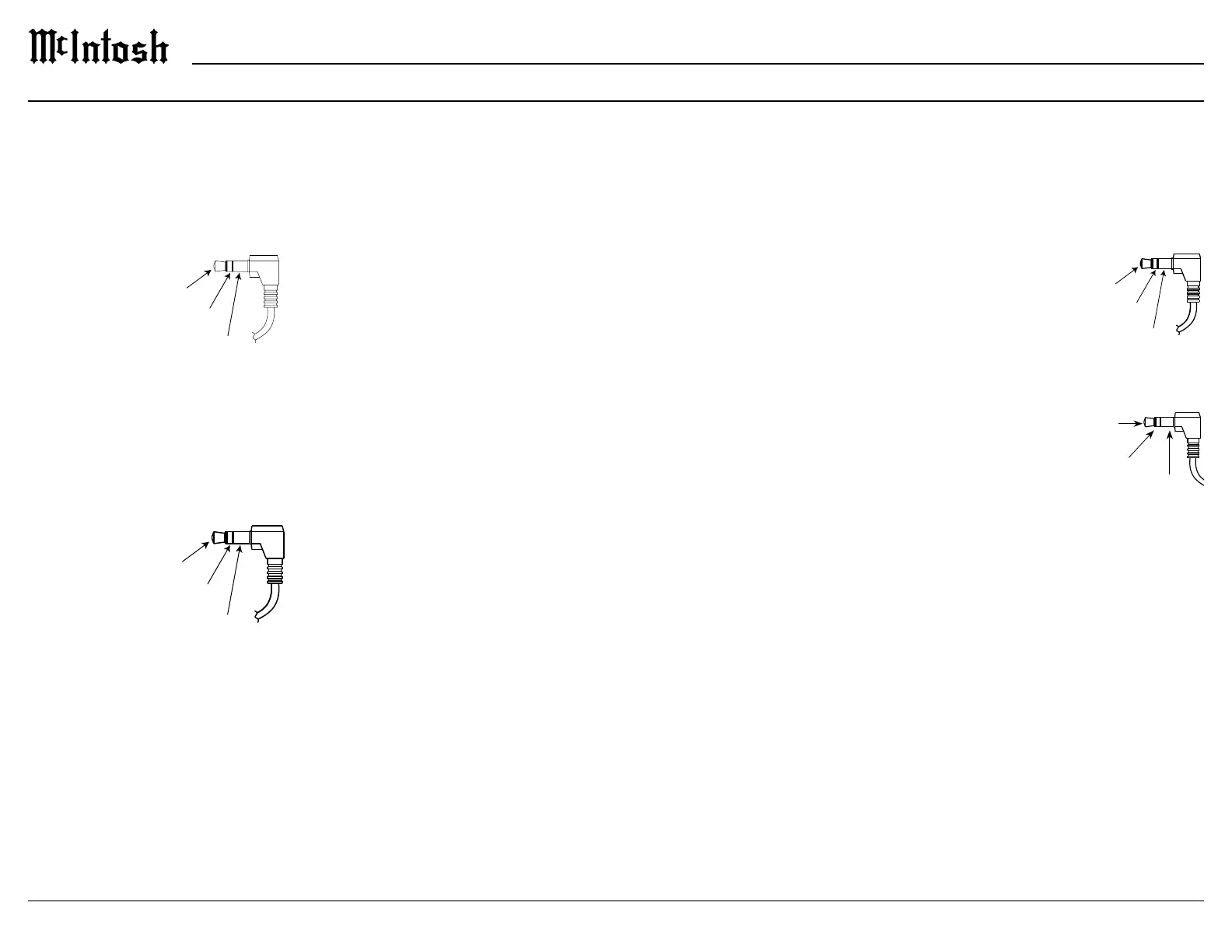
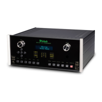
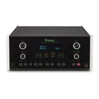
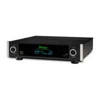
Connector and Cable Information
Data
Signal
N/C
Data
IR Data
Control
Ground
N/C
HDMI
video. To take advantage of this new capability, the
backward compatible, older cables may have issues
with the higher bandwidth.
television.
functions to ensure audio and video are perfectly
matched. This allows for more intelligent operation
between components as well as less cable clutter.
menu.
Atmos and DTS:X.
USB
The USB port is not for
general USB use or charging devices.
Microphone
microphone is used in the Dirac Live
®
calibration for
tuning the system to your room. For instructions see
“Dirac Live® Setup” on page 22.
IR IN Port Connector
the remote control can be used in another location
IR sensors such as a Xantech
Note: The IR receiver must provide its own
power supply.
RS232
controllers.
Typical RS232 settings are:
•
one stop bit
•
bits per second
AC Power
This connection is essential. Plug the supplied
Data being transmitted
Data being received
Power
l
Lighting
l