22 McQuay OM 920-1
Keypad/Display Menu Structure
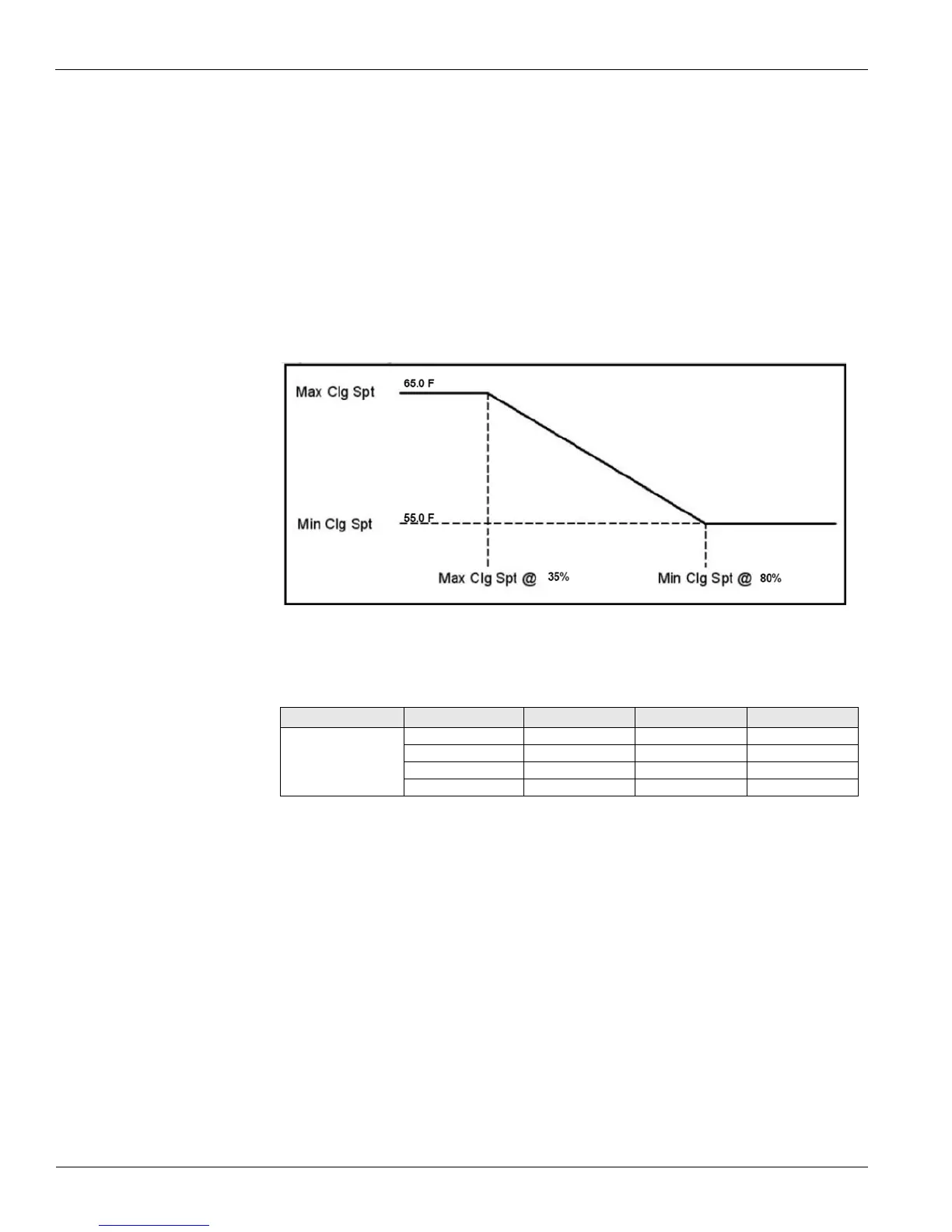
Figure 5 graphically shows the cooling reset operation. Example, The normal DAT cooling
setpoint is 55.0 F. The cooling reset scheme is set to airflow. The unit is to adjust the DAT
from 55.0 F to 65.0 F. When the unit is at 35% of the design airflow the discharge temperature
is to be 65.0 F. When the unit is at 80% of its airflow the DAT is to be 55.0F. This example
would give the following inputs:
Min Clg Spt = 55.0 F
Min Clg Spt @ = 80%
Max Clg Spt = 65.0 F
Max Clg Spt @ = 35%
Based on the above, the unit will have a discharge air temperature setpoint of 55.0 F from 80%
to 100% of the airflow.
Figure 5: Cooling Setpoint
Head Pressure Menu
The Head Pressure menu contains parameters that are used to maintain head pressure control.
WRV Pos is a status only item that indicates the current water regulating valve position.
Head P Circ 1 is a status only item that indicates the current refrigerant pressure for circuit
#1.
Head P Circ 2 is a status only item that indicates the current refrigerant pressure for circuit
#2.
Setpoint is an adjustable item that sets the refrigerant setpoint used for controlling the water
regulating valve. The water-regulating valve is modulated to maintain the refrigerant pressure.
Note – This section only applies to Self Contained units with a water regulating valve.
Table 11: Head Pressure Menu
Menu Display Name Item Display Name Default Setting Range Password Level
Head Pressure WRV Pos= - 0-100% 6
Head P Circ 1= - 0-750psi 6
Head P Circ 2= - 0-750psi 6
Setpoint= 260psi 230-340psi 6