IM-738 Page 71
Variable Frequency Drive Operation
Refer to the vendor instructions supplied with the unit.
Convenience Receptacle/Section Lights
A convenience receptacle is provided in the main control box
on all units. To utilize this receptacle, a separate field supplied
115V power wiring circuit must be connected to the 115V field
terminal block TB1, located in the main control box. Note that
the National Electrical Code requires that this circuit be pro-
tected by a ground fault circuit interrupter (GFI) device.
Optional lights are available for certain sections in the unit.
Each light includes a switch and convenience receptacle, and is
powered by the external 115V power supply connected to TB1.
DesignFlow Outdoor Air Damper Option
DesignFlow™ airflow measurement stations are located inside
the louvered outdoor air intake doors between the intake lou-
ver and outside air dampers. Essentially, they consist of a vane
that is repositioned by airflow, the amount of rotation indicat-
ing the amount of airflow. They have been precision cali-
brated at the factory and no further calibration is required.
However, a leveling adjustment is required. The DesignFlow
unit must be accurately leveled so that when operating it will
be orientated the same as when it was calibrated.
The rotational position of the DesignFlow unit vane is trans-
lated into CFM by the microprocessor in the MicroTech II
control system. The position of the vane is determined by
two things - the force of the airflow impacting the vane and
the gravitational effect on the vane. Gravity is the only factor
at the lower CFM end of the range. On a correctly leveled
unit, this gravitational effect will be the same as when the
unit was calibrated in the factory.
Both the right-hand and left-hand DesignFlow stations must
be accurately leveled. To accurately level a station, a precise
mechanical force is applied against the vane. That force
should cause the vane to move to a specific position if the
DesignFlow unit is correctly leveled. If the vane does not
move to the correct position with the force applied, the
DesignFlow unit is not properly leveled and gravity is caus-
ing the difference.
The DesignFlow unit is mounted such that it pivots at the top.
A lock nut, a slotted hole, and a threaded adjuster allow posi-
tioning the bottom of the assembly so it can be correctly lev-
eled. When the lock nut is loosened, the threaded adjuster
allows precise, controlled movements. Make sure that power
has been supplied to the unit. The leveling component can be
found in the main control box.
DesignFlow Airflow Measurement
Station Startup:
Note: Before starting the station startup procedure, locate
the leveling components kit that can be found in the
main unit control box.
Note: Before starting the station startup procedures, verify
that power has been supplied to the unit’s Micro-
Tech II control system. The DesignFlow startup pro-
cedure cannot be completed without use of the
MicroTech II controls.
1. The swinging vanes on the measurement stations have been
locked in place for shipment. The stations are accessible
when the louvered outdoor air intake doors are opened.
Remove the two shipping screws from each vane. One
screw is located one inch from the top of the vane. The
other is one inch from the bottom of the vane. Both are
about eight inches in from the outer edge of the vane.
2. Examine the station for shipping damage. Manually rotate
the vane and verify that it does not rub against anything.
Close and latch the louvered intake door.
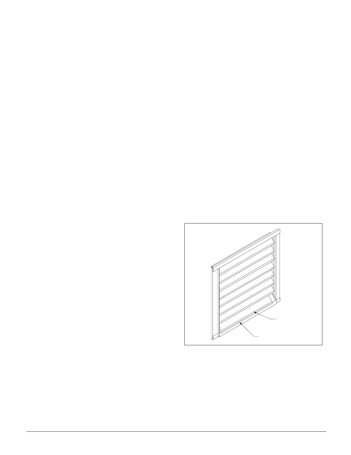
3. Remove the covers from the access opening in the bottom
blade of the outdoor air intake louvers (See Figure 76).
The leveling procedure must be accomplished with the
louvered door in the closed position. These openings pro-
vide access for leveling.
Figure 76. Remove Covers from Access Opening
4. The leveling procedure is performed with the fans off and
the outdoor air dampers closed. If there is a wind, the out-
door air louvers should be covered with poly film, card-
board, etc. to prevent adverse readings due to wind.
C o v e r
A c c e s s
O p e n i n g