Page 40 IM-738
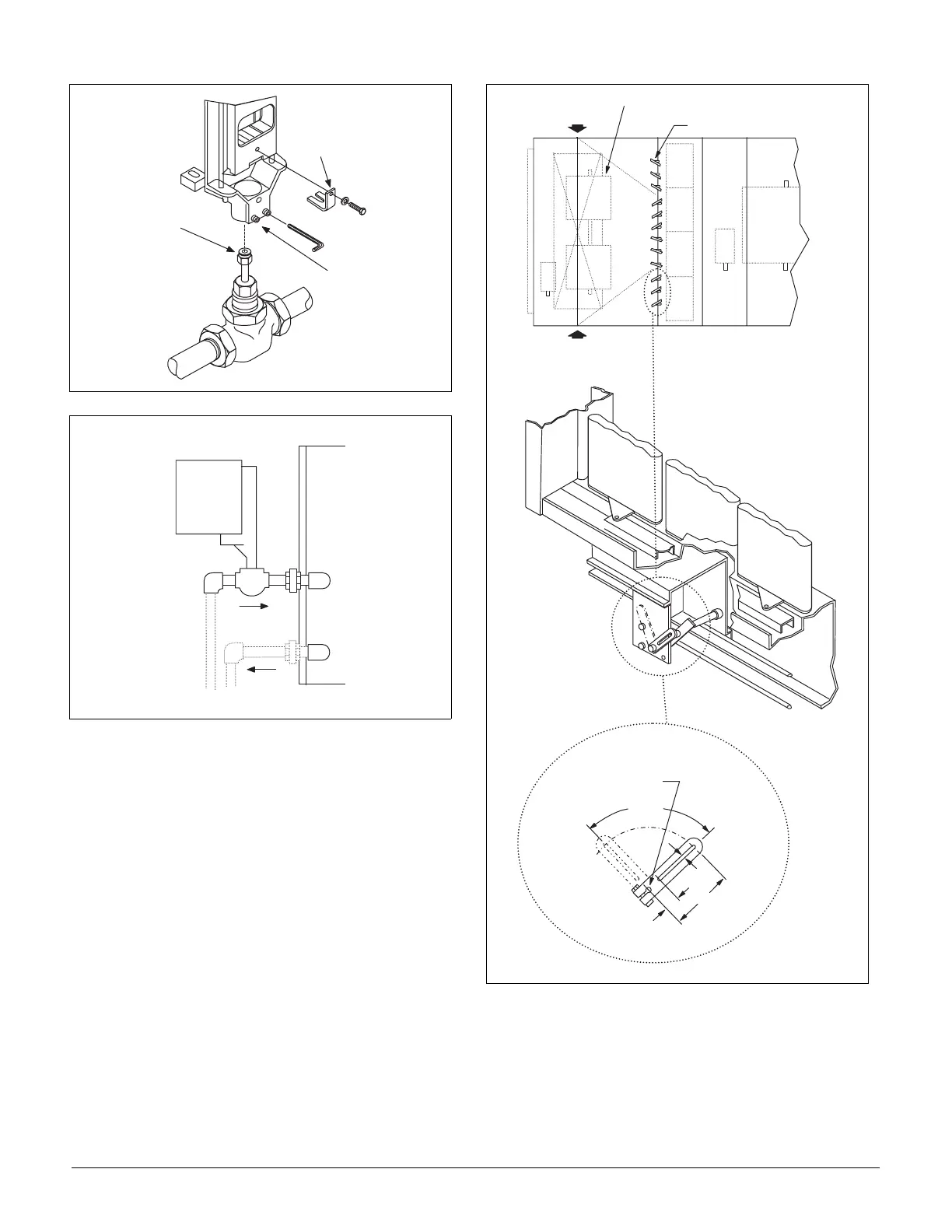
Figure 44. Valve Assembly
Figure 45. Steam Valve Package
Damper Assemblies
The optional damper assemblies described in this section are
provided with manually adjustable linkages, or may be
shipped with factory installed actuators and linkages.
Economizer Dampers
Outside air intake is provided on both sides of the unit, and the
return air path is at the center of the damper set. As the single
actuator modulates the outside air dampers open, the return air
dampers close. Exhaust air exits the unit through the gravity
relief dampers provided at the end of the economizer section.
The outside air return air damper assembly (economizer)
comes with manually adjustable linkage. This adjustable link-
age can also be used for connection of a damper operator.
The damper is set so that the crankarm moves through a 90-
degree angle to bring the economizer dampers from full open
to full close. Mechanical stops have been placed in the cran-
karm mounting bracket. Do not remove stops. If the crankarm
is driven past the stops, damage to the linkage or damper will
result. The unit will ship with a shipping bolt securing the link-
age crankarm. Remove shipping bolt before use.
Figure 46. Damper Adjustment
Note: For good airflow control, adjust linkages so damper
blades do not open beyond 70 degrees. Opening a
damper blade beyond 70 degrees has little effect on
its airflow.
Do not "overclose" low leak damper blades. The
edge seal should just lightly contact the adjoining
blade. The blades will lock up if they are closed so
far the seal goes over center.
S t e m
S e t s c r e w s
S t e m C l i p
R e t u r n
S u p p l y
O A
C l o s e d
O A
O p e n
3 . 0 0
. 2 5
. 7 5
9 0 °
S t r o k e
S h a f t . 5 0 0 D i a .
x 1 . 5 0 L o n g
O u t s i d e
A i r
O p t i o n a l R e t u r n A i r F a n
E c o n o m i z e r
O u t s i d e
A i r